background image

2

ENGLISH

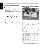
UNPACKING AND CHECKING PARTS

B

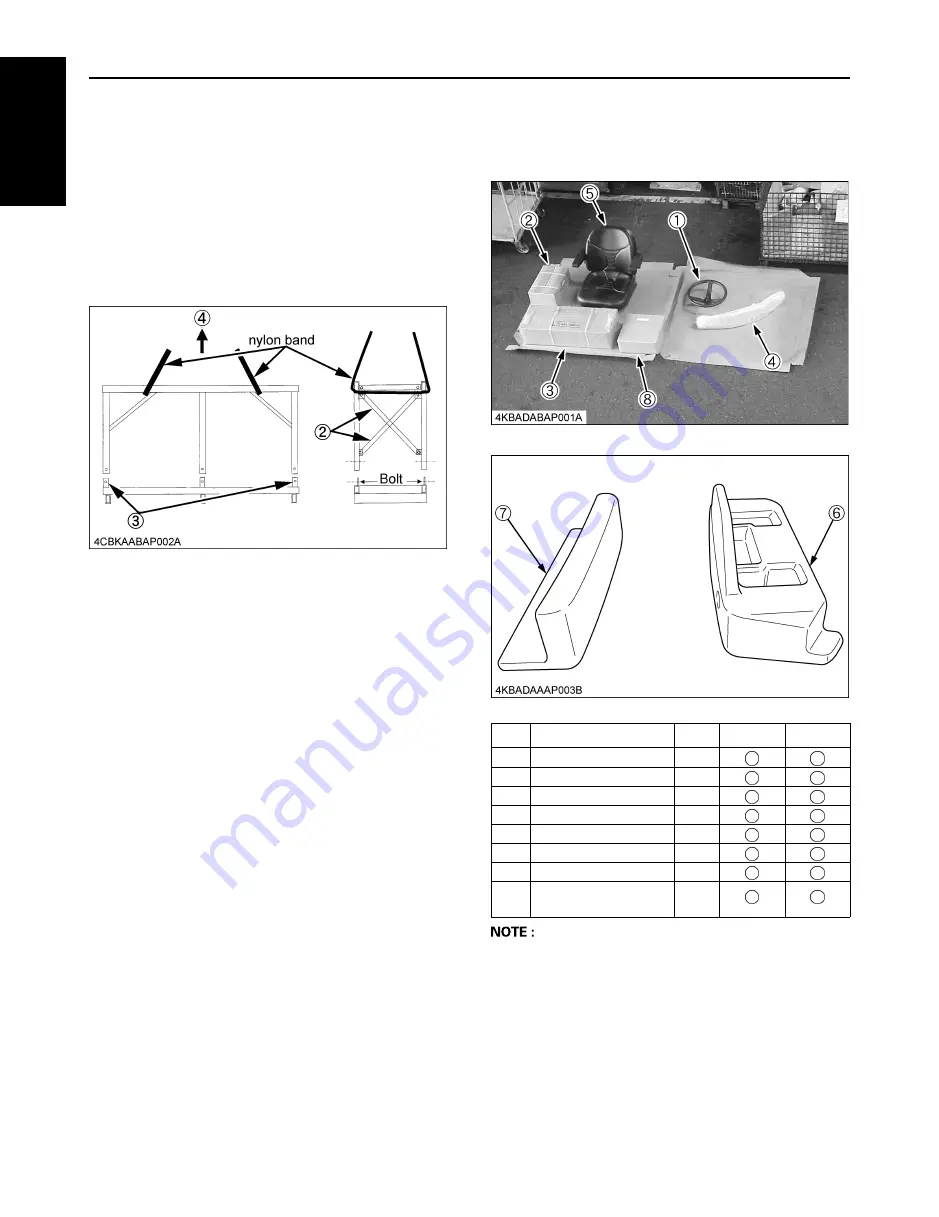
Unpacking Iron crate

1. Take the diagonal member out of the front of the iron

crate.

2. Take the 4 pieces of bolts (M10-1.25) out of both side

of the iron crate.

3. Tie up the iron crate with a nylon band and lift up with

a hoist or fork lift. (Be careful not to damage the
tractor.)

B

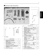
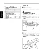
The Accessories Packaged Together With 

Tractor Models

A

FRONT / REAR TIRE are not included in the crate.

No.

DESCRIPTION

UNIT

F2880

F3680

(1)

STEERING WHEEL

1

(2)

ACCESSORY CASE

1

(3)

LINK, LH RH

1

(4)

FENDER, EXTENSION

1

(5)

SEAT

1

(6)

WEIGHT, LARGE

1

(7)

WEIGHT, SMALL

1

(8)

ASSY COVER 
(UNIVERSAL JOINT)

1

Summary of Contents for WSM F2880

Page 1: ...CTIONS INSTRUCTIONS POUR LE MONTAGE MODELS MODELES F2880 MODELLS F3680 1BDAIABAP0010 ENGLISH DEUTSCH FRANÇAIS PRINTED IN JAPAN IMPRIME AU JAPON DRUCK JAPAN Code No AN F 7 11 8 AK No de code K3623 6295 4 Code Nr KUBOTA Corporation 2005 ...

Page 2: ...cation are found throughout this manual in steps where particular attention is required so as to ensure your safety and to avoid product damage Observe the instructions in these warnings where indicated 3DANGER Indicates an imminently hazardous situation which if not avoided will result in death or serious injury 3WARNING Indicates a potentially hazardous situation which if not avoided could resul...

Page 3: ...se only adequate and required equipment tools and instruments torque wrench or battery hydrometer 3 Set the parking brake and place blocks in front of wheels when they re contacting the ground to prevent machine movement 4 Lower the attachment or implement to the ground before assembling or adjusting equipment 5 Before working under suspended or raised equipment support the equipment or attachment...

Page 4: ... Tie up the iron crate with a nylon band and lift up with a hoist or fork lift Be careful not to damage the tractor BThe Accessories Packaged Together With Tractor Models A FRONT REAR TIRE are not included in the crate No DESCRIPTION UNIT F2880 F3680 1 STEERING WHEEL 1 2 ACCESSORY CASE 1 3 LINK LH RH 1 4 FENDER EXTENSION 1 5 SEAT 1 6 WEIGHT LARGE 1 7 WEIGHT SMALL 1 8 ASSY COVER UNIVERSAL JOINT 1 ...

Page 5: ... LINK LIFT 2 5 SPRING LIFT 2 ASSY ROD LIFT SPRING 2 NUT 4 ATTACHING WEIGHT 6 COVER REAR 1 7 WASHER SPRING M12 2 NUT M12 2 WASHER PLAIN M12 2 BOLT M10 x 20 2 ATTACHING AUXILIARY WEIGHT BOLT M10 x 65 2 WASHER PLAIN M10 4 NUT M10 2 FRONT TIRE FITTING PARTS 8 NUT TAPER 10 HANDLE PARTS 9 ASSY PAD STEERING 1 REAR TIRE FITTING PARTS 10 WASHER SPRING M12 8 NUT M12 8 WASHER PLAIN M12 8 SEAT SECURING PARTS ...

Page 6: ...age 1 Align the axial center of right and left links 1 with that of outer link stay 2 Fix the shaft fulcrum 3 with the M12 tap bolts 4 one on each side BAttaching the Weight 1 Secure the rear cover 1 and the plate 11 to the machine with the two bolts 2 as shown in the figure below 2 Place the weight 3 on the rear cover Fix the weight with the two spring washers 4 two plain washers 5 and two nuts 6...

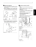
Page 7: ...rately Front Mower linkage Back Weight Apply the M18 bolts and nuts to the mower linkage A to prevent slipping Front hoisting positions Rear hoisting positions BFitting the Front Tires Attach the front tires to the front axle with the taper nuts five for each tire 48 1 to 55 9 N m 4 9 to 5 7 kgf m 35 4 to 41 2 ft lbs BFitting the Rear Tires Fix the rear tires 1 to the rear axle with the four M12 n...

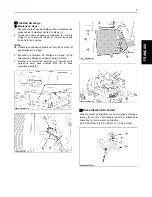
Page 8: ...oint pins 13 plain washers 7 and split pins 8 BSecuring the Seat C Fitting the seat 1 Connect the wire harness 2 to the OPC switch behind the seat 1 2 Put the four plastic collars 3 in between the seat 1 and seat base 4 Apply the four bolts 5 in place A Use the plastic collars 3 and the bolts 5 assembled to the seat 3 Connect the seat wire harness 2 to the main wire harness 6 of the machine 4 Moun...

Page 9: ...column and secure it with the nut 2 and spring washer 3 Attach the pad 4 onto the steering wheel 29 4 to 49 0 N m 3 0 to 5 0 kgf m 21 7 to 36 2 ft lbs BAttaching the Extension Fender Put the insert nut 1 into the machine and secure the extension fender 2 with the tapping screw 3 ...

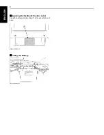
Page 10: ...8 ENGLISH BApplying the Hydraulic Caution Label Apply the hydraulic caution label 1 to the back of the seat base BFitting the Battery ...

Page 11: ...CTIONS INSTRUCTIONS POUR LE MONTAGE MODELS MODELES F2880 MODELLS F3680 1BDAIABAP0010 ENGLISH DEUTSCH FRANÇAIS PRINTED IN JAPAN IMPRIME AU JAPON DRUCK JAPAN Code No AN F 7 11 8 AK No de code K3623 6295 4 Code Nr KUBOTA Corporation 2005 ...

Page 12: ...uvent dans ce manuel lorsqu une attention particulière est requise pour assurer la sécurité du travail et éviter d endommager le produit Respecter les instructions dans ces avertissements lorsqu elles sont données 3 DANGER Indique une situation éminemment dangereuse des blessures graves ou la mort peuvent survenir si cette situation n est pas évitée 3 AVERTISSEMENT Indique une situation potentiell...

Page 13: ... instruments clé dynamométrique ou densimètre de batterie adéquats et requis 3 Serrer le frein de stationnement et mettre des cales devant les roues lorsqu elles touchent le sol pour éviter tout mouvement de la machine de la machine 4 Abaisser l accessoire ou l attachement au sol avant de monter ou d ajuster l équipement 5 Avant de travailler sous un équipement suspendu ou surélevé supporter l équ...

Page 14: ...moyen d une sangle en nylon et soulevez le avec un palan ou un chariot élévateur Faites attention de ne pas endommager le tracteur BAccessoires emballés avec les modèles de tracteurs A ROUES AVANT ARRIERE ne sont pas compris dans le cadre N DESCRIPTION UNITE F2880 F3680 1 VOLANT DE DIRECTION 1 2 CAISSE D ACCESSOIRES 1 3 BRAS GAUCHE DROIT 1 4 EXTENSION DE GARDE BOUE 1 5 SIEGE 1 6 GRAND CONTREPOIDS ...

Page 15: ...ROCHE D ARTICULATION 14 x 40 2 BROCHE D ARTICULATION 14 x 100 2 RONDELLE PLATE M14 8 GOUPILLE FENDUE 4 4 BRAS LEVAGE 2 5 RESSORT LEVAGE 2 ENS TRINGLE RESSORT DE LEVAGE 2 ECROU 4 FIXATION DU CONTREPOIDS 6 COUVERCLE ARRIERE 1 7 RONDELLE A RESSORT M12 2 ECROU M12 2 RONDELLE PLATE M12 2 BOULON M10 x 20 2 FIXATION DU CONTREPOIDS AUXILIAIRE BOULON M10 x 65 2 RONDELLE PLATE M10 4 ECROU M10 2 PIECES DE MO...

Page 16: ...éfaillance prématurée de la batterie BMontage des tirants de tondeuse 1 Alignez l axe des bras droit et gauche 1 sur celui de l appui extérieur des bras 2 Fixez l axe de pivotement 3 au moyen des boulons coniques M12 4 un de chaque côté N DESCRIPTION PIECES DE MONTAGE DES ROUES ARRIERE 10 RONDELLE A RESSORT M12 8 ECROU M12 8 RONDELLE PLATE M12 8 PIECES DE FIXATION DU SIEGE 11 FAISCEAU DE CABLAGE D...

Page 17: ...age de la tondeuse frontale Levage 1 Utilisez un engin ayant capacité de levage d au moins 1 tonne 2 Utilisez des élingues en nylon pour protéger la surface peinte de la tondeuse frontale 3 Cale ou cric Pour travailler sur la tondeuse frontale en position levée placez une cale ou un cric sous la machine pour l empêcher de tomber Position de levage de la tondeuse frontale Levez l avant et l arrière...

Page 18: ...m 7 0 à 7 4 kgf m 50 9 à 53 8 ft lbs BMontage des tirants de tondeuse 2 1 Attachez les tringles de levage 9 aux bras droit et gauche 1 et 2 et aux bras de levage avec les deux broches d articulation 5 et 6 les trois rondelles plates 7 et les deux goupilles fendues 8 2 Attachez le ressort de levage 10 et l ensemble de tringle de ressort de levage 11 à droite et à gauche respectivement 3 Montez le c...

Page 19: ...x en plastique 3 et les boulons 5 assemblés sur le siège 3 Branchez le faisceau de câblage du siège 2 au faisceau de câblage principal 6 de la machine 4 Montez le couvercle de pare choc 7 central sur le pare choc avec deux boulons M14 8 et deux rondelles plates 9 BRaccordement du volant Posez le volant de direction 1 sur la colonne et bloquez le avec l écrou 2 et la rondelle à ressort 3 Attachez l...

Page 20: ...prisonnier 1 sur la machine et fixez l extension de garde boue 2 avec la vis autotaraudeuse 3 BPose de l étiquette d avertissement du verrou hydraulique Apposez l étiquette d avertissement du verrou hydraulique 1 à l arrière du socle de siège BMontage de la batterie ...

Page 21: ...CTIONS INSTRUCTIONS POUR LE MONTAGE MODELS MODELES F2880 MODELLS F3680 1BDAIABAP0010 ENGLISH DEUTSCH FRANÇAIS PRINTED IN JAPAN IMPRIME AU JAPON DRUCK JAPAN Code No AN F 7 11 8 AK No de code K3623 6295 4 Code Nr KUBOTA Corporation 2005 ...

Page 22: ...ten ist die die Sicherheit des Bedieners sowie die Sicherheit der sich in der Nähe befindlichen Personen betrifft und um Schaden am Gerät zu vermeiden Befolgen Sie deshalb diese Warnhinweise in den bezeichneten Abschnitten 3 GEFAHR Dieses Zeichen weist auf die Möglichkeit einer äußerst gefährlichen Situation hin die zu einem schweren Unfall führen kann wenn sie nicht vermieden wird 3 WARNUNG Diese...

Page 23: ...ie Zusammenbauhinweise sorgfältig durchlesen um sich mit dem Gerät und den erforderlichen Arbeitsschritten vertraut zu machen 2 Nur die vorgeschriebenen für die Arbeiten geeigneten Komponenten Werkzeuge und lnstrumente verwenden Drehmonentschlüssel und Batterietester 3 Die Handbremse festziehen und die Vorderräder wenn auf dem Boden mit Klötzen absichern um ein ungewolltes Bewegen des Geräts oder ...

Page 24: ...g setzen AUSPACKEN UND TEILE PRÜFEN BAuspacken des Eisenbeschlags 1 Das diagonale Bauteil an der Front des Eisenbeschlags herausnehmen 2 Die 4 Schrauben M10 x 1 25 an beiden Seiten des Eisenbeschlages herausschrauben 3 Den Eisenbeschlag mit einem Nylonband anschlagen und ihn mit einem Kran oder Gabelstapler abheben Dabei vorsichtig sein und den Traktor nicht beschädigen ...

Page 25: ...ubehör A Vorder und Hinterräder sind im Verschlag nicht enthalten Nr BESCHREIBUNG ANZ F2880 F3680 1 LENKRAD 1 2 Zubehörkasten 1 3 Gestänge links rechts 1 4 Kotflügelverbreiterung 1 5 Sitz 1 6 Gewicht gross 1 7 Gewicht klein 1 8 Baugruppenabdeckung Kreuzgelenk 1 ...

Page 26: ...SCHRAUBE M12 x 25 2 VERBINDUNGSBOLZEN 14 x 40 2 VERBINDUNGSBOLZEN 14 x 100 2 UNTERLEGSCHEIBE M14 8 SPLINT 4 4 HUBGESTÄNGE 2 5 HEBEFEDER 2 HEBEFEDER STANGENBAUGR 2 MUTTER 4 ANBAUGEWICHT 6 HINTERE ABDECKUNG 1 7 FEDERSCHEIBE M12 2 MUTTER M12 2 UNTERLEGSCHEIBE M12 2 SCHRAUBE M10 x 20 2 ANBAU ZUSATZGEWICHT SCHRAUBE M10 x 65 2 UNTERLEGSCHEIBE M10 4 MUTTER M10 2 VORDERRÄDER MONTAGETEILE 8 KONUSMUTTER 10 ...

Page 27: ...d dies führt zu einem frühzeitigen Batterieausfall BMontage des Mähergestänges 1 Die axiale Mitte des rechten und linken Gestänges 1 mit der der äußeren Gestängestrebe 2 ausrichten Die Drehachse 3 mit den M12 Schrauben 4 eine auf jeder Seite montieren Nr BESCHREIBUNG HINTERRÄDER MONTAGETEILE 10 FEDERSCHEIBE M12 8 MUTTER M12 8 UNTERLEGSCHEIBE M12 8 SITZBEFESTIGUNGSTEILE 11 SITZSCHALTER KABELBAUM 1 ...

Page 28: ...ern 10 anschrauben BAnheben des Frontmähwerks Anheben 1 Einen Kran mit über 1 Tonne Hebeleistung verwenden 2 Um die beschichteten Oberflächen des Frontmähwerks zu schützen Nylonseile verwenden 3 Block oder Bock Wenn am angehobenen Frontmähwerk gearbeitet wird mit einem Block oder Bock das Mähwerk sichern Frontmähwerk Hebeposition Front und Rückseite separat anheben Front Mähergestänge Rückseite Ge...

Page 29: ...erachse montieren 69 0 bis 73 0 N m 7 0 bis 7 4 kgf m 50 9 bis 53 8 ft lbs BMontage des Mähergestänges 2 1 Das Hubgestänge 9 an den rechten und linken Gestängen 1 und 2 und den Hubarm mit zwei Verbindungsbolzen 5 und 6 drei Unterlegscheiben 7 und zwei Splinten 8 montieren 2 Die Hebefeder 10 und Hebefeder Stangenbaugruppe 11 jeweils links und rechts montieren 3 Die Abdeckung 12 mit den Verbindungsb...

Page 30: ... angebrachten Plastikbünde 3 und Schrauben 5 benutzen 3 Den Sitzkabelbaum 2 am Hauptkabelbaum 6 des Fahrzeugs anschließen 4 Die mittlere Kotflügelabdeckung 7 mit zwei M14 Schrauben 8 und zwei Unterlegscheiben 9 befestigen BMontage des Lenkrades Das Lenkrad 1 auf die Lenksäule setzen und mit der Mutter 2 und der Federscheibe 3 festschrauben Das Polster 4 auf dem Lenkrad montieren 29 4 bis 49 0 N m ...

Page 31: ... Die Einsatzmutter 1 in der Maschine einsetzen und die Kotflügelverbreiterung 2 mit den Blechschrauben 3 anschrauben BAnbringen des Hydraulik Warnschilds Das Hydraulik Warnschild 1 auf der Rückseite des Sitzsockels anbringen BBatterie Ausstattung ...

Reviews: