2. Move both motion control levers to the
“NEUTRAL
LOCK”
position.
3. Apply the parking brake.
4. Move the throttle lever to the half speed position
and push the PTO switch to the
“DISENGAGE”
(OFF) position.
5. Lower all implements to the ground.
6. Turn off the engine and remove the key.
IMPORTANT :
• Do not stop the engine when the machine is
on an incline for a long time. The engine oil
may go into the carburetor and the muffler
through the valve system.
• Before stopping the engine, place the
throttle control lever in the half speed
position to help prevent the engine from
backfiring.
PARKING THE MACHINE
WARNING
To avoid serious injury or death:
Before leaving the operator's position:
• Apply the parking brake.
• Lower all implements to the ground.
• Shut off the engine.
• Remove the key.
• Place the motion control levers in the
“NEUTRAL LOCK” position.
To apply:
Place the parking brake lever in the
“ENGAGED”
position.
To release:
Place the parking brake lever in the
“DISENGAGED”
position.
If necessary to park on an incline, be sure to chock the
wheels on the downhill side to prevent accidental rolling
of the machine.
(1) Chock
TRANSPORTING THE MACHINE
IMPORTANT :
• To transport the machine on a trailer:
– Turn the carburetor fuel valve to the “OFF”
position.
– Fasten the machine to the trailer.
• Do not attempt to tow this machine, or damage
to the transmission may result.
• When transporting the machine over a long
distance:
– Make sure to set the cutting height at
108 mm (4.25 in.) position. (Do not lock.)
1. Hydrostatic transaxle bypass rods
WARNING
To avoid serious injury or death:
• Do not touch the muffler or exhaust pipes while
they are hot. Severe burns could result.
IMPORTANT :
• Do not push the machine without pulling the
bypass rods, or transmission damage may
occur.
• Never pull the rods with the engine running.
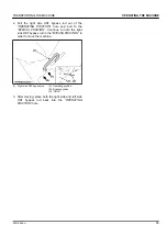
1. While facing the machine from the rear, pull the left
side HST bypass rod out of the
“OPERATING
POSITION”
hole and place it into the
“BYPASS
POSITION”
hole.
(1) Left side HST bypass rod
(A) Operating position
(B) Bypass position
OPERATING THE MACHINE
PARKING THE MACHINE
34
Z231KW-AU
Summary of Contents for Z231KW-AU
Page 7: ...4 Z231KW AU ...
Page 13: ...SAFETY LABELS SAFE OPERATION 10 Z231KW AU ...
Page 14: ...SAFE OPERATION Z231KW AU 11 ...
Page 15: ...SAFE OPERATION 12 Z231KW AU ...
Page 16: ...SAFE OPERATION Z231KW AU 13 ...
Page 66: ... 1 Cutting height fine tuning bolt 2 Jam nut MOWER DECK LEVEL ADJUSTMENT Z231KW AU 63 ...

