background image

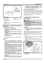
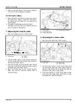
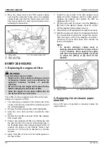
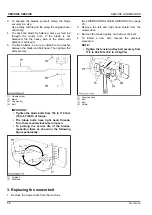
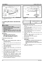
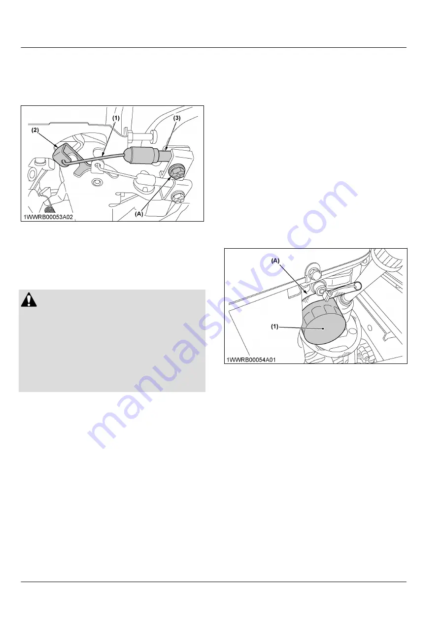
4. Move  the  choke  knob  to  the 

“ON”

  position.  Make

sure  that  the  carburetor  choke  valve  is  completely
closed.  Make  sure  that  the  choke  valve  turns  from
fully  closed  position  to  fully  opened  position  when
actuating the choke knob.

(1) Choke cable
(2) Choke control lever
(3) Choke cable sheath

(A) Choke cable clamp bolt

EVERY 200 HOURS

1. Replacing the engine oil filter

 WARNING

To avoid serious injury or death:

• Engine oil is a toxic substance. Dispose of used

oil  properly.  Contact  your  local  authorities  for
approved  disposal  methods  or  possible
recycling.

• Be sure to stop the engine and remove the key

before changing the oil and the oil filter.

• Allow  the  engine  to  cool  down  sufficiently.  Oil

can be hot and may cause burns.

The oil filter must be changed every 200 service hours.
Always use a genuine oil filter.

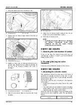
1. The drain plug is located on the starter side of the

oil pan. Clean the area around the oil drain plug and
the oil fill cap/dipstick.

2. Remove the drain plug and the oil fill cap/dipstick.
3. Allow  the  oil  to  drain  and  then  reinstall  the  drain

plug.

4. Remove the old filter and wipe off the filter adapter

with a clean cloth.

5. Place a new replacement filter in a shallow pan with

the open end up. Pour new oil, of the proper type, in
the threaded center hole. Stop pouring when the oil
reaches  the  bottom  of  the  threads.  Allow  a  few
minutes or 2 for the oil to be absorbed by the filter
material.

6. Apply a thin film of clean oil to the rubber gasket on

the new oil filter.

7. Install  the  new  oil  filter  to  the  filter  adapter.  Hand

tighten  the  filter  clockwise  until  the  rubber  gasket
contacts  the  adapter,  then  tighten  the  filter  an
additional 3/4 to 1 turn.

8. Fill  the  engine  with  the  proper  oil  to  the 

[FULL]

  or

[F]

 mark on the dipstick. Always check the oil level

with the dipstick before adding more oil.

9. Reinstall the oil fill cap/dipstick and tighten securely.
10. Start the engine and check for oil leakage. Recheck

the  oil  level  before  placing  the  engine  into  service.
Stop  the  engine,  correct  any  leakage,  and  allow  1
minute  for  the  oil  to  drain  down,  then  recheck  the
level on the dipstick.

NOTE :

• To  prevent  extensive  engine  wear  or

damage, always maintain the proper oil level
in  the  crankcase.  Never  operate  the  engine
with the oil level below the [ADD] or [L] mark
or  above  the  [FULL]  or  [F]  mark  on  the
dipstick.

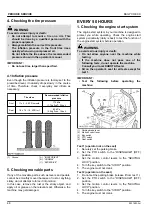
(1) Engine oil filter

(A) “MOUNTING SURFACE”

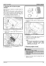
2. Replacing the air cleaner paper

element

Every  200  hours  of  operation  or  annually  replace  the
paper element.

 PERIODIC SERVICE

EVERY 200 HOURS

54

Z231KW-AU

Summary of Contents for Z231KW-AU

Page 1: ...AY A 2 2 AK PRINTED IN U S A KUBOTA Corporation 2019 English Australia Code No K3004 7125 1 Z 2 3 1 K W A U OPERATOR S MANUAL READ AND SAVE THIS MANUAL 1WJLE00001A01 Z231KW AU MODEL ...

Page 2: ...ment architecture construction and transportation Thousands of people depend on KUBOTA s know how technology experience and customer service You too can depend on KUBOTA Abbreviations Definitions API PTO RH LH ROPS rpm SAE American Petroleum Institute Power Take Off Right hand and left hand sides are determined by facing in the direction of forward travel Roll Over Protective Structures Revolution...

Page 3: ...l system It will give you long satisfactory service To obtain the best use of your machine please read this manual carefully It will help you become familiar with the operation of the machine and contains many helpful hints about machine maintenance It is KUBOTA s policy to utilize as quickly as possible every advance in our research The immediate use of new techniques in the manufacturing of prod...

Page 4: ...HECK DURING OPERATING 26 1 Fuel gauge 26 2 Hour meter 27 COLD WEATHER STARTING 27 WARMING UP THE ENGINE 27 1 Warm up and transmission oil in the low temperature range 27 JUMP STARTING 28 OPERATING THE MACHINE 29 OPERATING A NEW MACHINE 29 1 Changing lubricating oil for new machine 29 2 Engine break in 29 STARTING THE MACHINE 29 1 Operator s seat 30 2 Seat belt 30 3 Light switch if equipped 30 4 Mo...

Page 5: ...fler and spark arrester if equipped 47 EVERY 100 HOURS 48 1 Changing the engine oil 48 2 Cleaning the air cleaner paper element 49 3 Cleaning engine shroud 49 4 Checking the spark plug 50 5 Checking the fuel filter 50 6 Checking the battery condition 51 6 1 Charging the battery 52 6 2 Storing the battery 53 7 Adjusting the throttle cable 53 8 Adjusting the choke cable 53 EVERY 200 HOURS 54 1 Repla...

Page 6: ...e motion control levers 60 MOWER DECK LEVEL 60 1 Anti scalp rollers 60 2 Leveling the mower deck side to side 61 3 Leveling the mower deck front to rear 62 GENERAL TORQUE SPECIFICATION 64 TIGHTENING TORQUE CHART 65 STORAGE 66 STORING THE MACHINE 66 REMOVING THE MACHINE FROM STORAGE 66 TROUBLESHOOTING 67 ENGINE TROUBLESHOOTING 67 BATTERY TROUBLESHOOTING 69 MACHINE TROUBLESHOOTING 69 MOWER TROUBLESH...

Page 7: ...4 Z231KW AU ...

Page 8: ...he machine The clothing may catch on moving parts or controls leading to the risk of an accident Wear and use any additional safety items such as a hard hat safety boots or shoes eye and hearing protection gloves and so on as appropriate or required Do not wear radio or music headphones while operating the machine Safe operation requires your full attention Carefully check the vicinity before oper...

Page 9: ...g on uneven terrain or before stopping Do not operate near ditches holes embankments or other terrain which may collapse under the machine s weight The risk of machine tip overs increases when the ground is loose or wet Park the machine on a firm and level surface Before you get off apply the parking brake place the motion control levers in their neutral lock positions disengage the PTO lower all ...

Page 10: ...for holes in the terrain and other hidden hazards Keep away from drop offs Uneven terrain could overturn the machine Tall grass can hide obstacles Follow the manufacturer s recommendations for wheel weight or counterweights to improve stability Keep all movement on slopes slow and gradual Do not make sudden changes in speed or direction Avoid starting or stopping on a slope If tires lose traction ...

Page 11: ...illed water as required so that the fluid level is between the UPPER and LOWER levels Keep a first aid kit and fire extinguisher handy at all times Do not attempt to mount a tire on a rim unless qualified to do so and all proper safety precautions are followed Always maintain the correct tire inflation pressure Do not inflate tires above the recommended pressure shown in the operator s manual Prov...

Page 12: ...children or others from playing or tampering with them To avoid sparks from an accidental short circuit always disconnect the battery s ground cable first and reconnect it last 1 Battery 2 Ground cable Positive terminal Negative terminal To avoid the danger of exhaust fume poisoning do not operate the engine indoors without adequate ventilation To reduce fire hazards clean the machine thoroughly b...

Page 13: ...SAFETY LABELS SAFE OPERATION 10 Z231KW AU ...

Page 14: ...SAFE OPERATION Z231KW AU 11 ...

Page 15: ...SAFE OPERATION 12 Z231KW AU ...

Page 16: ...SAFE OPERATION Z231KW AU 13 ...

Page 17: ...d or missing safety labels with new labels from your local KUBOTA Dealer If a component with safety label s attached is replaced with a new part make sure new label s is are attached in the same location s as the replaced component Attach new safety labels by applying on a clean dry surface and pressing any bubbles to the outside edge SAFE OPERATION 14 Z231KW AU ...

Page 18: ...OPS engine and mower serial numbers Locate the PIN and serial numbers now and record them in the space provided Date of purchase Name of dealer To be filled in by purchaser Type PIN Serial number Machine ROPS Engine Mower To be filled in by purchaser 1 Machine identification plate 2 Product identification number 1 ROPS serial number 1 Engine serial number 1 Mower identification plate 2 Mower seria...

Page 19: ...PPING THE MACHINE AND ITS PROCEDURE To put the machine out of service correctly follow the local rules and regulations of the country or territory where you scrap it If you have questions consult your local KUBOTA Dealer SERVICING OF MACHINE SCRAPPING THE MACHINE AND ITS PROCEDURE 16 Z231KW AU ...

Page 20: ...eight without fuel with mower deck kg lbs 282 621 Traveling system Tires Front 11 4 5 4PR smooth Rear 18 7 5 10 4PR Traveling speeds Forward mph km h 6 5 10 5 Reverse mph km h 4 6 4 Steering 2 hand levers Transmission 2 HST with gear Parking brake Hand lever applied released Min turning radius mm in 0 0 PTO Drive system Belt Clutch type Electric Specifications and design subject to change without ...

Page 21: ... cutting height Dial gauge Cutting width mm in 1067 42 Cutting height mm in 38 1 to 108 1 5 to 4 25 Weight approximation kg lbs 45 3 100 Blade spindle speed r s rpm 52 2 3133 Blade tip velocity m s fpm 89 8 17700 Blade length mm in 548 21 6 Number of blades 2 Dimensions Total length mm in 888 35 0 Total width mm in 1401 55 2 Total height mm in 293 5 11 6 SPECIFICATIONS 18 Z231KW AU ...

Page 22: ...ts which exceed the maximum specifications listed below or Implements which are otherwise unfit for use with the KUBOTA Machine Any malfunctions or failures of the machine resulting from use with improper implements are not covered by the warranty Weight limit table Unit Maximum loading weight Implement weight Wa Maximum total weight Front axle Wf Rear axle Wr Z231KW AU 83 kg 184 lbs 362 kg 798 lb...

Page 23: ...ntrol lever 24 Motion control lever 31 3 Seat belt 30 4 Cup holder 5 Operator s seat 30 6 ROPS 7 Mower lift pedal 31 8 Cutting height control dial 36 9 Key switch 25 10 Hour meter 27 11 PTO switch 38 12 Throttle lever 31 13 Light switch if equipped 30 14 Choke knob 25 INSTRUMENT PANEL AND CONTROLS INSTRUMENT PANEL SWITCHES AND HAND CONTROLS 20 Z231KW AU ...

Page 24: ...MOWER Illustrated contents 1 Anti scalp roller front bolt shift type 36 2 Discharge deflector 29 Discharge deflector 37 MOWER INSTRUMENT PANEL AND CONTROLS Z231KW AU 21 ...

Page 25: ... tires as shown in the figure 4 Place the mower deck at the right side of the machine 5 Slide the mower deck under the machine then lower mower lift links 6 Attach the lift links to the mower deck with attaching hardware 1 Lift link 2 Clevis pin 3 Snap ring P Out side 7 Attach the mower belt to the engine pulley Refer the belt routing 1 Mower belt 2 Engine pulley IMPORTANT Check to see that the mo...

Page 26: ...If necessary adjust the mower level and anti scalp rollers ADJUSTING THE MOWER See OPERATING THE MOWER on page 36 and ADJUSTMENT on page 59 DISMOUNTING THE MOWER DECK For dismounting the mower deck reverse the above procedures ADJUSTING THE MOWER MOWER MOUNTING Z231KW AU 23 ...

Page 27: ...age 5 GETTING ON AND OFF THE MACHINE SAFELY Do not step on either side of the mower deck when you get on and off the machine When you get on and off the machine from either side step over the mower deck STARTING THE ENGINE 1 Sit on the operator s seat 2 Apply the parking brake To apply the parking brake Place the parking brake lever in the ENGAGED position 1 Parking brake lever A ENGAGED B DISENGA...

Page 28: ...and the operator is sitting on the seat 8 Warm up the engine by running at medium speed 1 Choke knob Pull the choke knob to engage the choke Push in the choke knob to disengage the choke When the engine is cold Always engage the choke to start the engine in cold conditions The engine and equipment may be operated during the warm up period but it may be necessary to leave the choke partially on unt...

Page 29: ...is less than 15 5 remove the battery from the machine and store it somewhere warm until the next operation STOPPING THE ENGINE 1 After setting the engine throttle to SLOW turn the key switch to the OFF position 2 Remove the key 3 Do not leave the key switch at ON key in the ON position as the battery will discharge when the engine is not running 4 Apply the parking brake 5 Turn the carburetor fuel...

Page 30: ...this procedure until the engine starts 4 When the engine starts release the key to the ON position 5 Push in the choke knob CHOKE OFF position WARMING UP THE ENGINE WARNING To avoid serious injury or death Be sure to apply the parking brake during warm up For 5 minutes after the engine start up allow the engine to warm up without applying any load This is to allow oil to reach every part of the en...

Page 31: ...akes of both vehicles and put the shift levers in the neutral position Shut the engine off 3 Put on safety goggles and rubber gloves 4 Ensure that vent caps are securely in place if equipped 5 Attach the red clamp to the positive red or pos terminal of the dead battery and clamp the other end of the same cable to the positive red or pos terminal of the helper battery 6 Clamp the other cable to the...

Page 32: ...g the machine cannot be driven or controlled If the engine stops when operating on a slope apply the parking brake immediately to prevent a machine runaway Do not allow anyone other than the driver to ride on the machine Do not drive the machine close to the edges of ditches or banks which may collapse under the weight of the machine especially when the ground is loose or wet When making a turn be...

Page 33: ...erator s seat WARNING To avoid serious injury or death Make adjustments to the seat only while the machine is stopped Make sure that the seat is completely secured after each adjustment Do not allow anyone other than the driver to ride on the machine 1 Fore aft adjusting handle Fore aft adjustment Pull the seat adjusting lever and slide the seat Armrest if equipped The armrest may be set at the up...

Page 34: ...e Place the parking brake lever in the ENGAGED position To release the parking brake Place the parking brake lever in the DISENGAGED position 1 Parking brake lever A ENGAGED B DISENGAGED 7 Motion control lever WARNING To avoid serious injury or death Understand how to use the motion control levers and practice in an unrestricted area at slightly more than idle speed without the mower engaged until...

Page 35: ... serious injury or death No control is provided by the motion control levers when the engine is off Neutral position Grasp the motion control levers and move them inward from the NEUTRAL LOCK position so that the machine is in NEUTRAL the engine cannot be restarted Forward and rearward motion 1 Move the throttle lever to the FAST position 2 Release the parking brake 3 Move both motion control leve...

Page 36: ...mend that you contact your local KUBOTA Dealer STOPPING THE MACHINE WARNING To avoid serious injury or death Park the machine on level ground If necessary to park on an incline stop the machine apply the parking brake and then stop the engine If you stop the engine on an incline without applying the parking brake the machine could move and run away IMPORTANT The parking brake lever is for parking ...

Page 37: ... brake lever in the DISENGAGED position If necessary to park on an incline be sure to chock the wheels on the downhill side to prevent accidental rolling of the machine 1 Chock TRANSPORTING THE MACHINE IMPORTANT To transport the machine on a trailer Turn the carburetor fuel valve to the OFF position Fasten the machine to the trailer Do not attempt to tow this machine or damage to the transmission ...

Page 38: ...the right side HST bypass rod in the BYPASS POSITION in order to move the machine 1 Right side HST bypass rod A Operating position B Bypass position H HOLD 3 After moving place both the right side and left side HST bypass rod back into the OPERATING POSITION hole TRANSPORTING THE MACHINE OPERATING THE MACHINE Z231KW AU 35 ...

Page 39: ...les on the first trip around the obstacle 4 Most lawns should be mowed to keep the grass approximately 50 to 80 mm 2 to 3 in high Best results are obtained by cutting often and not too short To keep a green lawn never mow more than 1 3 of the height of the grass or a maximum of 25 mm 1 in in 1 mowing For extremely tall grass set the cutting height at maximum cutting height for the first mowing the...

Page 40: ...Never allow the rollers to contact the ground continuously as premature roller wear may develop if set incorrectly Anti scalp rollers must maintain a minimum clearance of 6 mm 0 25 in to the ground Bolt setting 1 Anti scalp roller front bolt shift type OPERATING THE MOWER DANGER To avoid serious injury or death Do not operate the mower without the discharge deflector being in place properly WARNIN...

Page 41: ...at shields or guards 1 Sit on the operator s seat Put on the seat belt Make sure that the parking brake is engaged 2 Start the engine 3 Engage the PTO switch 4 Disengage the parking brake 5 Speed up the engine by moving the throttle lever forward 6 Push or pull the motion control levers to move forward or rearward IMPORTANT Never attempt to move the machine with the parking brake ON NOTE Keep the ...

Page 42: ...rops slowly in the course of time Therefore check it everyday and inflate as necessary Tire sizes Recommended inflation pressure Front 11 x 4 5 4PR smooth 170 kPa 1 7 kgf cm2 25 psi Rear 18 x 7 5 10 4PR turf 83 kPa 0 9 kgf cm2 12 psi 1 Ground A INSUFFICIENT B NORMAL C EXCESSIVE WHEELS IMPORTANT When refitting a wheel tighten the wheel bolt to the following torques then recheck after traveling 200 ...

Page 43: ...eplacement wheel 2 Install the wheel bolt and the nut 3 Tighten the nut Tightening torque 48 to 56 N m 36 to 41 lbf ft 4 9 to 5 7 kgf m 4 Lower the machine IMPORTANT Make sure that a washer is set on wheel bolt side 1 Nut 2 Wheel bolt 3 Yoke 4 Washer 5 Cap with felt A Front wheel TIRES AND WHEELS WHEELS 40 Z231KW AU ...

Page 44: ...10 Spark plug Check every 100 hr 50 Replace every 1 year 56 11 Engine shroud Clean every 100 hr 49 12 Engine oil filter Replace every 200 hr 54 1 13 Combustion chamber Clean every 300 hr 55 3 14 Valve seats and clearance Clean every 300 hr 55 3 Adjust every 300 hr 55 15 Electric clutch Adjust every 500 hr or every 1 year 55 16 Fuel line Check every 1 year 56 4 Replace every 4 years 56 3 17 Engine ...

Page 45: ...lean fresh unleaded gasoline A minimum of 87 octane 87AKI 90 RON Gasoline with up to 10 ethanol ethyl or grain alcohol or up to 15 methyl tertiary butyl ether MTBE by volume is acceptable Do not use unapproved gasoline such as E85 Do not mix oil in gasoline or modify the engine to run on alternate fuels This will damage the engine components and void the engine warranty High altitude This engine m...

Page 46: ...k and service the machine on a level surface with the engine shut off the key removed and the parking brake securely set or the rear wheels chocked No Check item Ref page Walking around the machine 1 Damage to machine body tightness of all bolts nuts pins and so on 2 Fuel and oil leak 3 Tire pressure wear and damage 39 46 4 Engine oil level 44 5 Fuel level 44 6 Air intake screen 45 7 Air cleaner 4...

Page 47: ...oil to the prescribed level at the oil port if necessary 1 Engine oil port 2 Oil level dipstick A UPPER LEVEL B LOWER LEVEL IMPORTANT When using a different brand or viscosity oil from the previous one remove all of the old oil and the oil filter Never mix 2 different types of oil Use the proper SAE engine oil according to the ambient temperature See LUBRICANTS AND FUEL on page 42 2 Checking the a...

Page 48: ... storage container tightly and store it out of sunlight and heat to prevent fuel degradation Condensation in the fuel tank may occur because of various operating or environmental conditions To reduce condensation and to avoid affecting the machine operation fill the fuel tank at the end of daily operations Use of alcohol mixed gasoline Only use gasoline containing ethanol when the ethanol is 10 or...

Page 49: ... on the relevant spot Otherwise the machine may get damaged EVERY 50 HOURS 1 Checking the engine start system The engine start system in your machine is designed to protect you while operating Check the engine start system periodically daily is best to test the function of the engine start system before operation WARNING To avoid serious injury or death Do not allow anyone near the machine while t...

Page 50: ...y is best to test function of the OPC system before operation WARNING To avoid serious injury or death Do not allow anyone near the machine while testing If the machine does not pass one of the following tests do not operate the machine Consult your local KUBOTA Dealer 1 Parking brake lever 2 Motion control lever 3 Key switch 4 PTO switch 5 Seat switch Test 1 operator on the seat 1 Start the engin...

Page 51: ...ng the engine oil WARNING To avoid serious injury or death Be sure to stop the engine and remove the key before changing the oil Allow the engine to cool down sufficiently as oil can be hot and may cause burns After the first 8 hours change the engine oil 1 Insert the hose attached with the machine to the T type pipe fitting on the right side of the engine In case no hose attached use the hydrauli...

Page 52: ...per element A Air intake hose 1 Air cleaner paper element A Air intake hose 3 Clean the air cleaner base as required and check condition B Air cleaner base 4 Reinstall the air cleaner paper element into the air intake hose and reinstall them in place 5 Close the air cleaner cover NOTE Operating the engine with loose or damaged air cleaner components could allow unfiltered air into the engine causi...

Page 53: ... porcelain pitted electrodes or other wear and damage Replace the spark plug if necessary 1 Spark plug both sides 4 Check the spark plug gap with a gap gauge Recommended spark plug NGK BPR4ES A 0 75 mm 0 03 in 5 Checking the fuel filter WARNING To avoid serious injury or death Be sure to stop the engine and remove the key when attempting to make the following checks and changes Never fail to check...

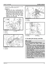
Page 54: ... A Muffler B Carburetor 6 Checking the battery condition DANGER To avoid the possibility of battery explosion For the refillable type battery follow these instructions Do not use or charge the refillable type battery if the fluid level is below the LOWER lower limit level mark Otherwise the battery component parts may prematurely deteriorate which may shorten the battery s service life or cause an...

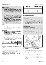
Page 55: ...intenance free non accessible batteries are designed to eliminate the need to add water Yet the volume of electrolyte above the plates may eventually become depleted due to abnormal conditions such as high heat or improper regulator settings Use a voltmeter to check the state of charge See the following reference chart to determine if charging is necessary Battery voltage Reference state of charge...

Page 56: ...he cable clamp bolt A 3 Pull up the sheath 3 of the throttle cable until the inner wire of the throttle cable has almost no slack and tighten the cable clamp bolt A 4 Move the throttle lever to the SLOW position Make sure that the carburetor throttle valve is moved smoothly 1 Throttle cable 2 Speed control lever 3 Throttle cable sheath A Throttle cable clamp bolt 8 Adjusting the choke cable 1 Move...

Page 57: ...ent filter in a shallow pan with the open end up Pour new oil of the proper type in the threaded center hole Stop pouring when the oil reaches the bottom of the threads Allow a few minutes or 2 for the oil to be absorbed by the filter material 6 Apply a thin film of clean oil to the rubber gasket on the new oil filter 7 Install the new oil filter to the filter adapter Hand tighten the filter clock...

Page 58: ...ailure EVERY 300 HOURS 1 Cleaning the combustion chamber If you do not have the proper tools and or are not mechanically proficient consult your local KUBOTA Dealer for this service 2 Checking the engine valve clearance Consult your local KUBOTA Dealer for this service EVERY 500 HOURS 1 Adjusting the electric clutch This adjustment should be done every 500 hours of operation or annually whichever ...

Page 59: ... too narrow the clutch armature may drag when disengaged resulting in premature failure EVERY 1 YEAR 1 Replacing fuel filter See Checking the fuel filter on page 50 2 Checking fuel lines See Checking the fuel filter on page 50 3 Checking the muffler and spark arrester if equipped See Checking the muffler and spark arrester if equipped on page 47 4 Replacing spark plug See Checking the spark plug o...

Page 60: ... or replacing the blades wipe grass and mud off the top and inside of the mower Especially clean inside the belt cover otherwise the belt life will be reduced Checking the blade The blade cutting edges should be kept sharp at all times 1 Sharpen the cutting edges if they look like the blade B 2 Replace the blades if they look like the blade C A New blade B Worn blade C Cracked blade Replacing 1 Di...

Page 61: ...from 103 to 118 N m 76 to 87 lbf ft of torque The blade bolts have right hand threads Turn them counterclockwise to loosen To prolong the service life of the blades reposition them as shown in the following figure periodically 1 LH blade 2 RH blade 3 Replacing the mower belt 1 Remove the mower deck from the machine See DISMOUNTING THE MOWER DECK on page 23 2 Remove the left and right hand shield f...

Page 62: ...achine frame 2 Remove both rear wheels 3 Start the engine and run at maximum speed 4 Place the motion control lever in the NEUTRAL LOCK position 5 Loosen the 3 bolts of the guide plate Adjust the guide plate position until the rear axle rotation stops 6 Tighten the rear bolt and place the lever in NEUTRAL LOCK position Check that the rear axle does not rotate If the axle does not stop rotating adj...

Page 63: ...pply the parking brake Lever position high or low 1 Remove the bolts and select the motion control lever position high or low 2 Tighten the bolts 1 Bolt 2 Flange nut 3 Tab slot A Low position Lever alignment right and left 1 Loosen the bolts 2 Slide both levers forward or rearward to the desired position within tab slots until the levers are aligned 3 Tighten the bolts MOWER DECK LEVEL 1 Anti scal...

Page 64: ...utside the blade tip to the level surface with a short ruler or leveling gauge Reference Height of the blade at the flat surface 76 mm 3 in NOTE There is a difference of blade height between flat surface and ground measurements 6 Check that the left side blade has the same height The difference between both measurements is less than 3 mm 0 125 in 7 If the side to side adjustment is not within the ...

Page 65: ...ft side blade has the same dimensions The difference between both measurements should be less than 6 mm 0 25 in The front side must be lower than the rear side 8 If the front to rear adjustment is not within the given tolerance adjustment is necessary A Front B Rear Front to rear adjustment Less than 6 mm 0 25 in The front side must be lower than the rear side Adjusting the level front to rear 1 R...

Page 66: ... 1 Cutting height fine tuning bolt 2 Jam nut MOWER DECK LEVEL ADJUSTMENT Z231KW AU 63 ...

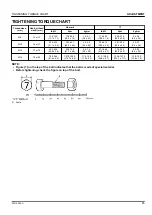
Page 67: ... 42 47 5 57 0 4 84 5 82 45 54 61 0 73 2 6 22 7 47 M10 lbf ft N m kgf m 35 5 41 2 48 1 55 8 4 9 5 7 44 9 52 1 60 8 70 5 6 2 7 2 1 2 lbf ft N m kgf m 80 96 108 5 130 2 11 07 13 29 110 132 149 2 179 0 15 22 18 27 M12 lbf ft N m kgf m 57 2 66 5 77 5 90 1 7 9 9 2 76 0 86 8 103 117 10 5 12 0 9 16 lbf ft N m kgf m 110 132 149 2 179 0 15 22 18 27 160 192 217 0 260 4 22 14 26 57 M14 lbf ft N m kgf m 91 2 1...

Page 68: ...41 2 38 3 2 9 48 1 55 9 52 0 3 9 4 9 5 7 5 3 0 4 M12 17 or 19 46 3 53 5 49 9 3 6 62 8 72 6 67 7 4 9 6 4 7 4 6 9 0 5 57 1 66 5 61 8 4 7 77 6 90 2 83 9 6 3 8 0 9 2 8 6 0 6 M14 19 or 22 79 6 92 6 81 6 6 5 107 9 125 5 116 7 8 8 11 0 12 8 11 9 0 9 91 1 108 5 99 8 8 7 123 6 147 0 135 3 11 7 12 6 15 0 13 8 1 2 NOTE Figure 7 on the top of the bolt indicates that the bolt is made of special material Before...

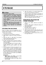
Page 69: ...hs in the cold season 7 Drain the fuel tank fuel lines and carburetor or use a fuel stabilizer to prevent deterioration of the gasoline If you choose to use a fuel stabilizer follow the manufacturers recommendations and add the correct amount for the capacity of the fuel system Fill the fuel tank with clean fresh gasoline Run the engine for 2 to 3 minutes to get stabilized fuel into the carburetor...

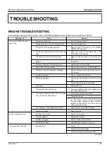
Page 70: ...BOTA Dealer Air cleaner clogged Clean or replace the air cleaner Spark plug damaged Adjust the spark plug gap or replace the spark plug Check the spark plug wire connection Fuse blown Replace the fuse The engine oil viscosity is wrong Use oils of different viscosities depending on the ambient temperature The battery becomes weak and the engine does not turn over quick enough Clean battery cables a...

Page 71: ...hoke position Exhaust fumes are colored white or blue Excessive engine oil Reduce to the specified oil level Piston ring worn or stuck See your KUBOTA Dealer Engine overheats Engine overloaded Lower speed or reduce load Engine oil insufficient Fill engine oil The engine air intake screen and cooling fins are dirty Clean the air intake screen and cooling fins Air cleaner paper element plugged Clean...

Page 72: ... grease and treat with anti cor rosives The battery electrolyte level drops rapid ly There is a crack or pin holes in the elec trolytic cells Replace the battery Charging system trouble Contact your local KUBOTA Dealer If you have any questions contact your local KUBOTA Dealer MACHINE TROUBLESHOOTING Symptom if Cause Remedy The machine operation is not smooth The hydrostatic transaxle fluid is ins...

Page 73: ...er deck Uneven cut Mower deck not level Level the mower deck Ground speed too fast Slow down Blades dull Have blades sharpened Blades worn or damaged Replace the blades Low tire inflation Add air to correct pressure Anti scalp rollers not adjusted correctly Adjust the anti scalp rollers Wheels pressure not adjusted correctly Set both tire pressure to the correct pressure See TIRES on page 39 Blade...

Page 74: ...ottle check and reset the engine rpm Ground speed too fast Slow down Debris wrapped around mower spindles Clean the mower Front of deck too low Adjust the mower deck See MOWER DECK LEVEL on page 60 If you have any questions contact your local KUBOTA Dealer TROUBLESHOOTING Z231KW AU 71 ...

Page 75: ...ing 44 daily check list 43 E electric clutch adjusting 55 engine jump starting 28 operating warning information 24 starting 24 starting in cold weather 27 starting information 25 stopping 26 stopping immediately 26 troubleshooting 67 warming up 27 engine break in 29 engine oil changing 48 engine oil filter replacing 54 engine shroud cleaning 49 engine start system checking 46 engine valve clearanc...

Page 76: ...ing 61 mower lift pedal 31 mowing tips 36 muffler checking 47 56 O OPC system checking 47 operator s seat 30 lowering 43 raising 43 P parking brake applying 24 releasing 24 parking brake lever 31 PTO switch 38 S safety before operating the machine 5 general information 5 operating on slopes 7 ROPS 6 servicing the machine 8 starting to operate the machine 6 stopping the machine 7 storing the machin...

Reviews: