ADJUSTMENT
MOTION CONTROL LEVER
WARNING
To avoid serious injury or death:
• Park the machine on a firm and level surface.
• If it is necessary to run the engine indoors, use
a gas tight exhaust pipe extension to remove
the fumes.
• Always try to work in a well-ventilated area.
• Lift up and secure with jack stands or by
blocking the rear of the machine. Do not run the
machine while adjusting.
Remove the rear wheels.
• Do not make only one of the following
adjustments (except “MOTION CONTROL
LEVER ALIGNMENT”).
They are interlinked.
• If you feel you are unable to make the following
adjustments correctly and safely, contact your
local KUBOTA Dealer.
Details regarding motion control lever alignment can be
found in a different section.
(See Motion control lever alignment on page 71.)
IMPORTANT :
• Right and left motion control levers can be
adjusted independently.
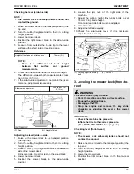
1. Adjusting the motion control lever
operating strength
The strength required to move the motion control levers
can be adjusted to 3 levels depending on operator
preference.
NOTE :
• Adjust the dampers after adjusting HST neutral.
• Adjusting the motion control lever strength will
affect the maneuverability.
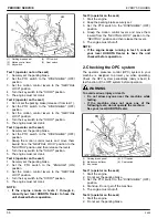
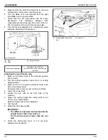
1. Change the upper side of the damper to the desired
hole location.
Tighten the upper side damper nut.
(1) Damper
(2) Nut
(A) “LIGHTER”
(B) “HEAVIER”
(H1) Hole for lighter setting
(H2) Hole for heavier setting
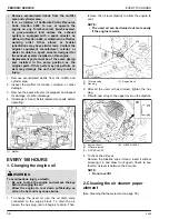
2. Loosen the nut on the bottom side of the damper.
3. Move the motion control lever to the rearmost
position and release the motion control lever.
4. After the motion control lever and damper have
stopped moving, place the motion control lever in
the
“NEUTRAL LOCK”
position.
5. Tighten the bottom side damper nut.
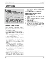
2. HST neutral
1. Lift up and secure with jack stands or by blocking
the rear of the machine frame.
2. Remove both rear wheels.
3. Start the engine and run at maximum speed.
4. Place the motion control lever in the
“NEUTRAL
LOCK”
position.
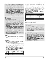
5. If either rear axle is turning, observe the following
steps to adjust the neutral position.
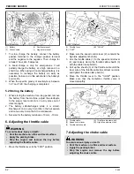
6. Loosen the 3 bolts of the guide plate corresponding
to the rotating axle (LH or RH).
Adjust the guide position until the rear axle rotation
stops.
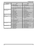
7. Tighten the rear guide plate bolt and check that the
rear axle does not rotate.
If the axle does not stop rotating, adjust the
“HST
NEUTRAL”
again.
Tightening torque
23.6 to 27.4 N
⋅
m (2.4 to
2.8 kgf
⋅
m, 17.4 to 20.2 lbf
⋅
ft)
8. Adjust the opposite side axle
“HST NEUTRAL”
if
required.
ADJUSTMENT
MOTION CONTROL LEVER
70
Z400
Summary of Contents for Z411
Page 3: ...OPERATOR S MANUAL 1SFRT00108A01 READ AND SAVE THIS MANUAL MODELS Z411 Z421 Z421T ...
Page 9: ...4 Z400 ...
Page 16: ...SAFETY LABELS SAFE OPERATION Z400 11 ...
Page 17: ...SAFE OPERATION 12 Z400 ...
Page 18: ...SAFE OPERATION Z400 13 ...
Page 19: ...SAFE OPERATION 14 Z400 ...
Page 20: ...SAFE OPERATION Z400 15 ...
Page 53: ...PERIODIC SERVICE CHART LABEL MAINTENANCE PERIODIC SERVICE CHART LABEL 48 Z400 ...

