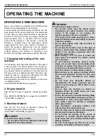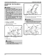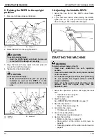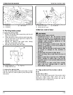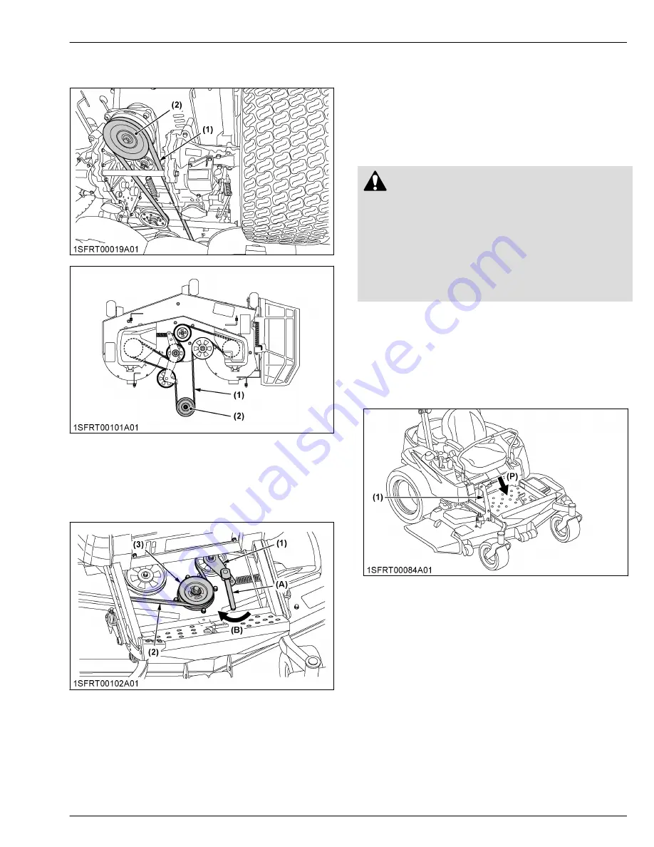
8. Raise the mower deck to 76 mm (3.0 in.) or higher.
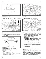
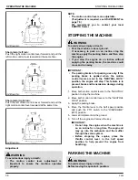
Attach the PTO belt to the PTO clutch pulley.
(1) PTO belt
(2) PTO clutch pulley
9. Remove the step.
(See OPENING THE STEP on page 50.)
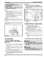
10. Turn the tension arm clockwise with a square
wrench.
(1) Tension arm
(2) Mower belt
(3) Mower pulley
(A) Square wrench
(B) “CLOCKWISE”
11. Attach the mower belt to the mower pulleys.
12. After mounting the mower, check the mower level. If
necessary, adjust the mower level and anti-scalp
rollers.
ADJUSTING THE MOWER
(See OPERATING THE MOWER on page 41 and
ADJUSTMENT on page 70.)
DISMOUNTING THE MOWER
DECK
WARNING
To avoid serious injury or death:
• Push the mower deck lift pedal with enough
strength. If the strength is not enough, the
mower link will jump up when the Φ9.5 mm
(0.37 in.) shaft is removed from the right side of
the machine due to the power of the spring.
• Keep all hands and feet clear of the mower links
during this time.
1. Raise or lower (as needed) the mower deck to a
cutting height of 76 mm (3.0 in.) or higher.
2. Remove the mower belt.
3. Adjust the cutting height control dial to the 38.1 mm
(1.5 in.) position.
(See ADJUSTING THE CUTTING HEIGHT on page
41.)
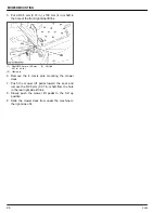
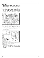
(1) Mower lift pedal
(P) “PUSH”
4. Adjust the anti-scalp rollers to the 38.1 mm (1.5 in.)
position.
(See ADJUSTING THE CUTTING HEIGHT on page
41.)
ADJUSTING THE MOWER
MOWER MOUNTING
Z400
25
Summary of Contents for Z411
Page 3: ...OPERATOR S MANUAL 1SFRT00108A01 READ AND SAVE THIS MANUAL MODELS Z411 Z421 Z421T ...
Page 9: ...4 Z400 ...
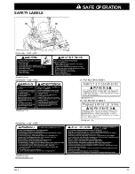
Page 16: ...SAFETY LABELS SAFE OPERATION Z400 11 ...
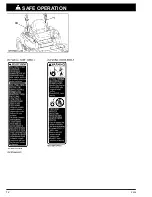
Page 17: ...SAFE OPERATION 12 Z400 ...
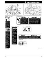
Page 18: ...SAFE OPERATION Z400 13 ...
Page 19: ...SAFE OPERATION 14 Z400 ...
Page 20: ...SAFE OPERATION Z400 15 ...
Page 53: ...PERIODIC SERVICE CHART LABEL MAINTENANCE PERIODIC SERVICE CHART LABEL 48 Z400 ...

