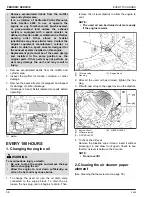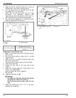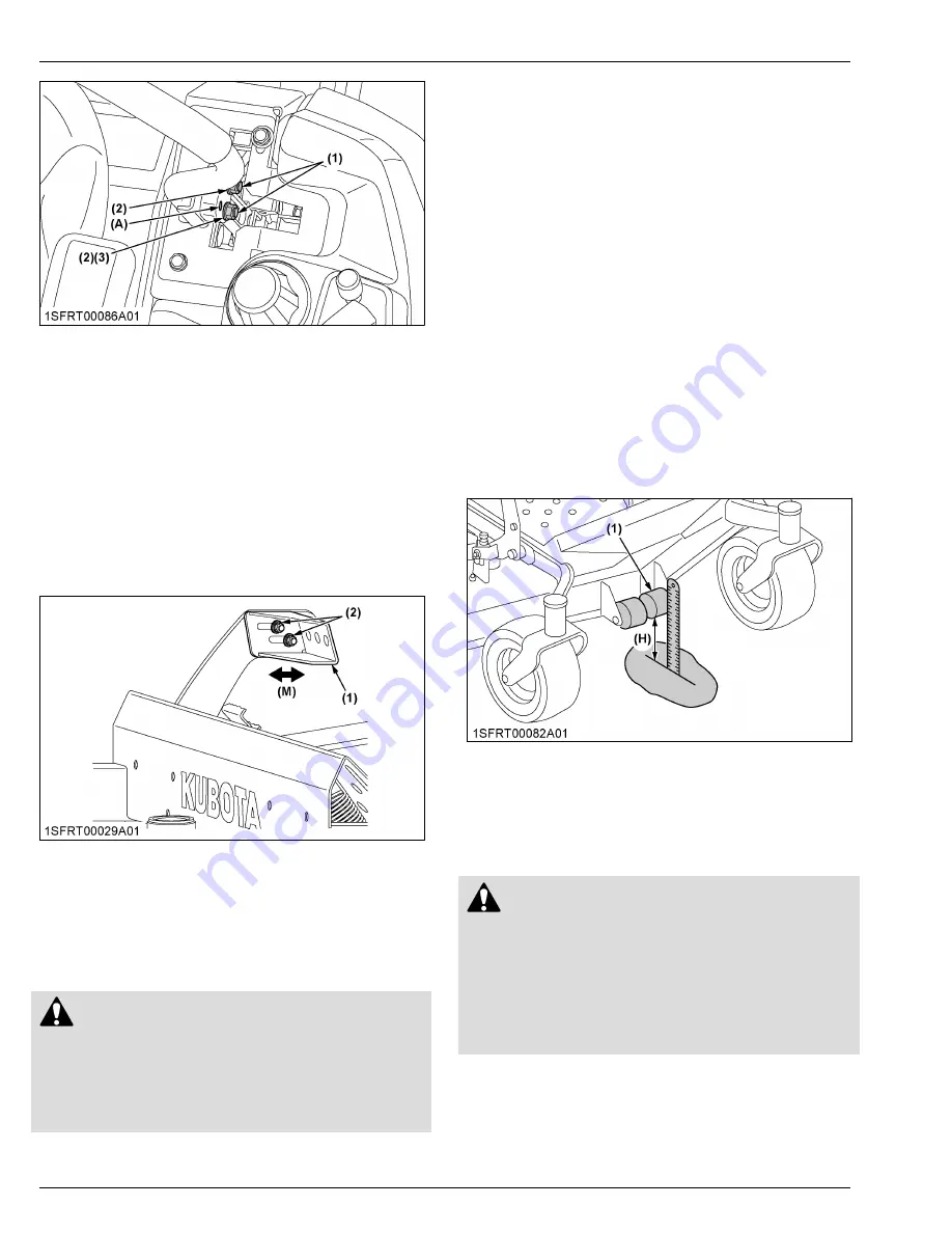
(1) Bolt
(2) Flange nut
(3) Tab slot
(A) High position
Lever alignment (right and left)
1. Loosen the bolts.
2. Slide both levers forward or rearward to the desired
position within tab slots until the levers are aligned.
3. Tighten the bolts.
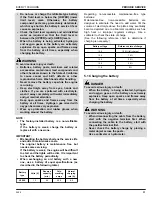
5. Adjusting the mower lift pedal
1. Stop the engine and apply the parking brake.
2. Loosen the nut and adjust the pedal position.
(1) Pedal
(2) Nut (M8)
(M) “MOVE”
3. Tighten the nuts.
MOWER DECK LEVEL
1. Anti-scalp rollers
WARNING
To avoid serious injury or death:
• Park the machine on a firm and level surface.
• Apply the parking brake.
• Stop the engine and remove the key.
• Wait for all moving parts to stop.
NOTE :
• The flattest cut can be achieved by having the
anti-scalp rollers adjusted off the ground.
Check the anti-scalp roller adjustments each
time the mower deck cutting height is changed.
It is recommended that all the anti-scalp rollers
be kept off the ground to minimize scuffing.
1. Check the machine tire pressure.
Inflate tires to the correct pressure.
(See TIRES AND WHEELS on page 44.)
2. Start the engine.
3. Raise up the mower deck to the transport position
(the top end of the lift).
4. Turn the cutting height control dial to adjust the
height.
5. Lower the mower deck.
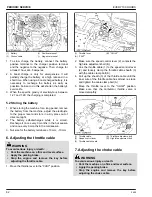
6. Adjust the height of the front side anti-scalp roller to
1 of the 4 positions, to approximately 19 mm
(0.75 in.) between the rollers and the ground.
Adjust the other 3 rollers to the same height.
(1) Front side anti-scalp roller
(H) 19 mm (0.75 in.)
7. Install the roller with the attaching hardware.
2. Leveling the mower deck (side-to-
side)
WARNING
To avoid serious injury or death:
• Park the machine on a firm and level surface.
• Apply the parking brake.
• Disengage the PTO (OFF).
• Stop the engine and remove the key while
checking or adjusting the level of the mower
deck.
IMPORTANT :
• Check the machine tire pressure.
Inflate the tires to the correct pressure.
(See TIRES AND WHEELS on page 44.)
ADJUSTMENT
MOTION CONTROL LEVER
72
Z400
Summary of Contents for Z411
Page 3: ...OPERATOR S MANUAL 1SFRT00108A01 READ AND SAVE THIS MANUAL MODELS Z411 Z421 Z421T ...
Page 9: ...4 Z400 ...
Page 16: ...SAFETY LABELS SAFE OPERATION Z400 11 ...
Page 17: ...SAFE OPERATION 12 Z400 ...
Page 18: ...SAFE OPERATION Z400 13 ...
Page 19: ...SAFE OPERATION 14 Z400 ...
Page 20: ...SAFE OPERATION Z400 15 ...
Page 53: ...PERIODIC SERVICE CHART LABEL MAINTENANCE PERIODIC SERVICE CHART LABEL 48 Z400 ...

