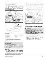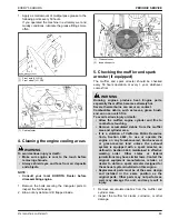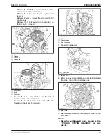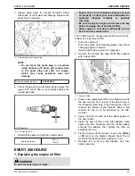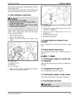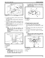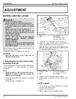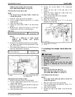
• Remove the 4 bolts that secures the base of the
air cleaner assembly and remove.
• Remove the screws securing the regulator and
remove.
• Remove 2 bolts to remove the oil cooler. (850 V
engine only)
• Remove the 3 bolts securing the fan guard so
that it can be removed.
(1) Air cleaner
(2) Clamp
(3) Oil cooler
(4) Fan guard
(1) Air cleaner
(2) Bolt
(3) Regulator
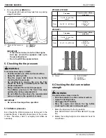
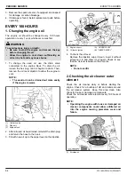
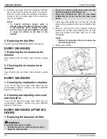
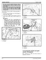
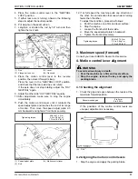
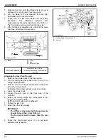
2. Remove the 4 torx bolts which secure the air inlet
screen so that it can be removed.
Remove the 3 bolts located on the side of the fan
housing so that it can be removed.
(1) Torx bolt
(2) Bolt
(3) Fan housing
(4) Air inlet screen
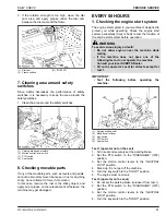
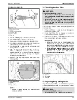
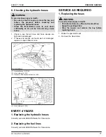
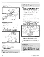
3. Cover the intake port.
(1) Intake port
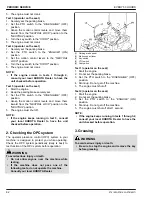
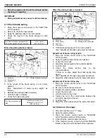
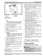
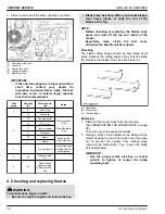
4. Blow out any contaminants such as debris or dust
from the cooling fan and engine body.
(1) Blow here
5. Reinstall all parts in the reverse order of the above
procedure.
NOTE :
• Refer to your Kawasaki engine manual, section
“COOLING SYSTEM CLEANING” for more
details.
EVERY 100 HOURS
PERIODIC SERVICE
Z751KWi,Z781KWi,Z781KWTi
69
Summary of Contents for Z751KWi
Page 3: ...OPERATOR S MANUAL 1SJGJ00001A01 READ AND SAVE THIS MANUAL MODELS Z751KWi Z781KWi Z781KWTi ...
Page 15: ...SAFETY LABELS SAFE OPERATION 10 Z751KWi Z781KWi Z781KWTi ...
Page 16: ...SAFE OPERATION Z751KWi Z781KWi Z781KWTi 11 ...
Page 17: ...SAFE OPERATION 12 Z751KWi Z781KWi Z781KWTi ...
Page 18: ...SAFE OPERATION Z751KWi Z781KWi Z781KWTi 13 ...
Page 19: ...SAFE OPERATION 14 Z751KWi Z781KWi Z781KWTi ...
Page 21: ...16 Z751KWi Z781KWi Z781KWTi ...

