background image

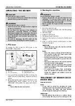
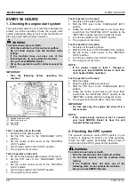
• Never  operate  the  engine  without  heat  shields

or guards.

IMPORTANT :

• The  air  intake  area  must  be  clear  of  debris  to

prevent the engine from overheating.

Daily  or  after  every  5  hours  of  operation,  check  to  be
sure the radiator screen and the hood screen are clean.
Dirt  or  chaff  on  the  radiator  screen,  hood  screen  or
radiator decrease cooling performance.

1. Remove  the  radiator  screen  and  the  hood  screen,

and remove all foreign material.

2. Remove  the  dust  from  between  the  fins  and  the

tube.

3. Tighten  the  fan  drive  belt  as  necessary.  Details

regarding this procedure can be found in a different
section.
(See Adjusting fan drive belt tension on page 71.)

4. If  the  scale  forms  in  the  tube,  clean  with  the  scale

inhibitor or its equivalent.

5. Each  time  the  hood  screen  is  covered  with  grass

during operation, rub it off the screen with the hand.
Check the radiator screen from time to time if grass
accumulates.

6. If  the  dust  or  chaff  has  accumulated  inside  of  the

hood,  remove  the  radiator  screen  and  clean  inside
completely.
After  cleaning,  replace  the  radiator  screens
properly.

7. Check the radiator for dust or chaff build up.

If the dust or chaff has accumulated in the radiator,
clear  with  air  pressure  (not  to  exceed  30  psi)  or  a
hose.

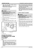
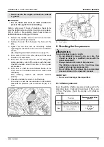
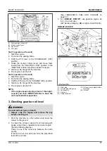
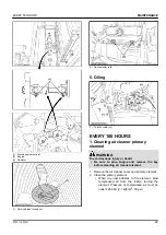
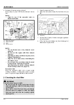
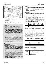
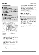
(1) Radiator screen

(1) Hood screen

6. Checking the tire pressure

 WARNING

To avoid serious injury or death:

• Do  not  attempt  to  mount  a  tire  on  a  rim.  This

should  be  done  by  a  qualified  person  with  the
proper equipment.

• Always maintain the correct tire pressure.

The  inflation  pressure  in  the  front  tires  rises
quickly when using compressed air.
Do not inflate the tires above the recommended
pressure shown in the operator's manual.

IMPORTANT :

• Do not use tires larger than specified.

6.1 Inflation pressure

Even though the inflation pressure is factory-set to the
prescribed level, it naturally drops slowly in the course
of  time.  Therefore,  check  it  everyday  and  inflate  as
necessary.

Tire sizes

Recommended inflation

pressure

Front

15 × 6.5 to 8, Smooth sem-

ipneumatic low profile tire

Rear

26 × 12.0 to 16, 4PR turf

low profile tire

83 kPa

0.84 kgf/cm

2

12 psi

LUBRICANTS, FUEL AND COOLANT

 PERIODIC SERVICE

ZD1211,ZD1221

61

Summary of Contents for ZD1211-60

Page 1: ... Corporation 2019 English Australia Code No K3444 7126 1 Z D 1 2 1 1 A U Z D 1 2 2 1 R A U Z D 1 2 2 1 L A U Z D 1 2 2 1 R L A U OPERATOR S MANUAL READ AND SAVE THIS MANUAL MODELS ZD1211 AU ZD1221R AU ZD1221L AU ZD1221RL AU 1SDNT00001A01 ...

Page 2: ...BOTA s know how technology experience and customer service You too can depend on KUBOTA UNIVERSAL SYMBOLS As a guide to the operation of your machine various universal symbols have been utilized on the instruments and controls The symbols are shown below with an indication of their meaning Safety Alert Symbol Diesel Fuel Fuel Level Parking Brake Engine Stop Preheat Engine Run Starter Control Power...

Page 3: ...l system It will give you long satisfactory service To obtain the best use of your machine please read this manual carefully It will help you become familiar with the operation of the machine and contains many helpful hints about machine maintenance It is KUBOTA s policy to utilize as quickly as possible every advance in our research The immediate use of new techniques in the manufacturing of prod...

Page 4: ...ey switch 29 STOPPING THE ENGINE 29 1 Engine stop lever inside the hood 29 CHECK DURING OPERATING 29 1 Easy Checker 29 LCD MONITOR 30 1 Fuel gauge 30 2 Coolant temperature gauge 31 3 Hour meter 31 4 Battery voltage meter 31 5 Service code display 31 6 Overheat alarm 32 7 Fuel gauge warning lamp and fuel valve 32 COLD WEATHER STARTING 32 WARMING UP THE ENGINE 32 1 Warm up and transmission oil in th...

Page 5: ...ENTING GRASS CLIPPINGS AND DUST FROM SCATTERING 48 1 Rubber plates installation 48 TIRES AND WHEELS 50 TIRES 50 1 Inflation pressure 50 WHEELS 50 1 Removing the front caster wheels 50 2 Installing the front caster wheels 51 PERIODIC SERVICE 52 OPENING THE HOOD FRONT COVER AND STEP 52 1 Hood 52 2 Front cover 52 3 Step 52 RAISING AND LOWERING THE OPERATOR S SEAT 52 TILTING UP THE MACHINE 53 OPENING ...

Page 6: ...le gear case oil RH and LH 77 2 Replacing hydraulic oil filter 78 3 Replacing fuel filter 79 EVERY 800 HOURS 79 1 Adjusting engine valve clearance 79 EVERY 1000 HOURS OR EVERY 1 YEAR 79 1 Replacing air cleaner primary element and secondary element 79 EVERY 1500 HOURS 80 1 Checking fuel injection nozzle injection pressure 80 EVERY 2000 HOURS OR EVERY 2 YEARS 80 1 Flushing cooling system and changin...

Page 7: ...ligning the motion control levers 88 MOWER DECK LEVEL 88 1 Anti scalp rollers 88 2 Leveling the mower deck side to side 89 3 Leveling the mower deck front to rear 90 GENERAL TORQUE SPECIFICATION 92 TIGHTENING TORQUE CHART 93 STORAGE 94 STORING THE MACHINE 94 REMOVING THE MACHINE FROM STORAGE 94 TROUBLESHOOTING 96 ENGINE TROUBLESHOOTING 96 POWER TRAIN TROUBLE SHOOTING 97 BATTERY TROUBLESHOOTING 98 ...

Page 8: ...ating the machine Do not operate the machine or any attachments while using or texting with a cellphone or any other electronic device Safe operation requires your full attention Carefully check the vicinity before operating machine or any implement attached to it Clear the work area of objects such as wires and rocks that might be picked up and thrown Check for overhead clearance which may interf...

Page 9: ...the seat belt when the ROPS is upright Do not use the seat belt if the ROPS is down or if there is no ROPS Check the seat belt regularly and replace if frayed or damaged Be certain that the seat belt can be released quickly in the event of an emergency 1 ROPS 2 Seat belt OPERATING THE MACHINE 1 Starting to operate the machine Always sit in the operator s seat when starting the engine or operating ...

Page 10: ...rate abnormally disengage the drive to the attachments stop the engine and remove the key Then check the machine immediately Do not operate the machine when there is a possibility of lightning Even if the machine is equipped with a cabin the operator is not protected from lightning Never raise the deck with the blades running Disengage the PTO and stop the blades from rotating if not mowing 3 Safe...

Page 11: ...deck installed 6 Stopping the machine Park the machine on level ground Make sure that the machine and all attachments have come to a complete stop before you get off Before you get off apply the parking brake place the motion control levers in their neutral lock positions disengage the PTO lower all attachments to the ground turn off the engine and remove the key Do not park the machine on dry gra...

Page 12: ...ner rather than from a fuel dispenser nozzle Keep the nozzle in contact with the rim of the fuel tank or container opening at all times until fueling is complete Do not use a nozzle lock open device If fuel is spilled on clothing change the clothing immediately Replace the fuel cap and tighten securely Charge batteries in an open well ventilated area away from spark and flames A battery especially...

Page 13: ...at lines pipes and hoses are not damaged Fluid escaping from pinholes may be invisible Use a piece of cardboard or wood to search for suspected leaks do not use hands Use safety goggles or other eye protection If you get injured by escaping fluid see a medical doctor at once Serious infection or reaction will result if proper medical treatment is not administered immediately This fluid can produce...

Page 14: ...d emergency response techniques The seller of the chemical products used with your machine is responsible for providing the MSDS for that product upon request 2 Storage Keep the machine and supply of fuel in locked storage and remove the ignition key to prevent children or others from playing or tampering with them To avoid sparks from an accidental short circuit always disconnect the battery s gr...

Page 15: ...SAFETY LABELS SAFE OPERATION 12 ZD1211 ZD1221 ...

Page 16: ...SAFE OPERATION ZD1211 ZD1221 13 ...

Page 17: ...SAFE OPERATION 14 ZD1211 ZD1221 ...

Page 18: ...SAFE OPERATION ZD1211 ZD1221 15 ...

Page 19: ...or missing safety labels with new labels from your local KUBOTA Dealer If a component with safety label s attached is replaced with a new part make sure new label s is are attached in the same location s as the replaced component Attach new safety labels by applying on a clean dry surface and pressing any bubbles to the outside edge SAFE OPERATION 16 ZD1211 ZD1221 ...

Page 20: ...ive your dealer the product identification number PIN and the ROPS engine and mower serial numbers Locate the PIN and serial numbers now and record them in the space provided Date of purchase Name of dealer To be filled in by purchaser Type PIN Serial number Machine ROPS Engine Mower To be filled in by purchaser 1 Machine identification plate 2 Product identification number 3 ROPS serial number 1 ...

Page 21: ...t been handled according to the instructions given in the operator s manual even if it is within the warranty period SCRAPPING THE MACHINE AND ITS PROCEDURE To put the machine out of service correctly follow the local rules and regulations of the country or territory where you scrap it If you have questions consult your local KUBOTA Dealer SERVICING OF MACHINE WARRANTY 18 ZD1211 ZD1221 ...

Page 22: ... 7 6 0 Engine coolant L U S qts 3 5 3 7 Recovery tank L U S qts 0 25 0 26 Transmission case includ ing rear axle gear case L U S qts 12 1 12 8 4 Dimensions Overall length mm in 2260 89 0 2380 93 7 Overall width without mower deck mm in 1510 59 4 1540 60 6 Overall height With ROPS upright mm in 2000 78 7 With ROPS folded mm in 1640 64 6 Wheelbase mm in 1440 56 7 1560 61 4 Min ground clearance mm in...

Page 23: ... 1200Z RCK72P 1200Z RCK72RP 1200Z PRO commer cial deck fabri cated deck Suitable machine ZD1211 AU ZD1221R AU ZD1221L AU ZD1221RL AU Mounting method Quick joint parallel linkage Adjustment of cutting height Dial gauge Cutting width mm in 1524 60 0 1829 72 0 Cutting height mm in 25 to 127 1 0 to 5 0 Weight approximation kg lbs 150 331 145 320 170 375 Blade spindle speed r s rpm 55 9 3355 1 52 4 314...

Page 24: ... not covered by the warranty Unit Maximum loading weight Implement weight W1 Maximum total weight Front axle Wf Rear axle Wr ZD1211 AU ZD1221R AU ZD1221L AU ZD1221RL AU 200 kg 440 lbs 920 kg 2028 lbs 200 kg 440 lbs 1120 kg 2468 lbs Option When using the hitch kit IMPORTANT Do not operate on slope when pulling loads Total towed weight must not exceed combined weight of pulling machine ballast and o...

Page 25: ...ttle lever 27 38 14 PTO clutch indicator 27 15 Neutral indicator Motion control lever 27 16 Parking brake warning indicator 27 17 Master system warning indicator 29 18 Glow plug indicator 29 19 Engine oil pressure warning indicator 29 20 Engine overheat warning indicator 29 21 Electrical charge warning indicator 29 22 Fuel level warning lamp 29 32 23 Coolant temperature gauge 31 24 Hour meter 31 2...

Page 26: ...i scalp roller rear bolt shift type rear RH roller is only for RCK72P 44 3 Discharge deflector 4 Gear box RCK60R RCK72R 1 Anti scalp roller front swivel type 44 2 Anti scalp roller rear bolt shift type 44 3 Gear box MOWER INSTRUMENT PANEL AND CONTROLS ZD1211 ZD1221 23 ...

Page 27: ...TILTING UP THE MACHINE on page 53 4 Place the mower deck at the left side of the machine 1 Gear box 5 Slide the mower deck under the machine and make sure that the mower gear box is placed properly in the center of the machine lower the axle from the TILT UP position to the NORMAL position 6 Place 50 mm 2 in wood blocks under each side of the mower deck 7 Depress the hydraulic lift control pedal D...

Page 28: ...E MOWER DECK For dismounting the mower deck reverse the above procedures INSTALLING PARTS TO THE MOWER 1 Installation of skid RCK60R RCK72R Install the skid with 5 flange bolts NOTE Right side shown left side similar 1 Skid right 2 Flange bolt M10 2 Installation of gauge wheel RCK60P RCK72P Install the anti scalp roller to the stay 3L gauge with gauge wheel boss sems bolt and locking nut IMPORTANT...

Page 29: ... THE CUTTING HEIGHT on page 44 NOTE Left side of RCK72R shown right side of RCK72R and both side of RCK60R similar Install the sems bolt from inside 1 Gauge wheel 2 Skid Left 3 Gauge wheels boss 4 Plain washer 5 Sems bolt 6 Locking nut 3 Installation of bolt adjuster 1 Install the bolt adjuster with the nut 2 Adjust length L 3 Tighten the nut 1 Bolt adjuster 2 Nut L 25 mm reference MOWER MOUNTING ...

Page 30: ...er deck STARTING THE ENGINE 1 Sit on the operator s seat Put on the seat belt 2 Apply the parking brake To apply the parking brake a Depress the parking brake pedal firmly with your right foot and the parking brake lock pedal simultaneously with your left foot b Then release the parking brake pedal while holding the parking brake lock pedal down c Parking brake warning indicator will come on 1 Par...

Page 31: ... the engine is being preheated 8 Turn the key switch to the START position and release the key to the ON position when the engine starts IMPORTANT Do not use starting fluid or ether To protect the battery and the starter make sure that the starter is not continuously turned for more than 10 seconds Do not turn the key switch while the engine is running When the temperature is below 0 32 run the en...

Page 32: ...e hood The engine stops when the key switch is turned off If the engine does not stop make sure the motion control levers are in the NEUTRAL LOCK position the PTO lever is off the mower lowered to the ground and apply the parking brake then carefully get off the machine Then open the hood and pull engine stop lever and hold it until the engine stops Then contact your local KUBOTA Dealer immediatel...

Page 33: ...onsult your local KUBOTA Dealer 5 Fuel level warning lamp If the fuel in the tank goes below the prescribed level the warning lamp in the Easy Checker will come on If this should happen during operation refuel as soon as possible See Checking the amount of fuel and refueling on page 59 IMPORTANT When the fuel warning lamp lights up refuel the tank as soon as possible If the machine runs out of fue...

Page 34: ...for the hours the machine has been operated 1 The hour meter indicates in 5 digits the hours the machine has been used the last digit indicates 1 10 of an hour 1 Hours used 4 Battery voltage meter This meter gives readings for the battery voltage Specification Battery voltage 12 0 V If the battery voltage is below 12 0 V charge the battery 1 Battery voltage meter 5 Service code display The key swi...

Page 35: ... case you have a small amount of fuel if fuel is still in the fuel tank RH fill the fuel tank LH first The fuel gauge shows the fuel level of fuel tank RH When the fuel gauge flashes fill fuel as soon as possible When the fuel gauge flashes do not fill fuel on a slope Fuel can absorb air and the engine can stall If the engine stalled with some remaining in the fuel tank RH close the fuel valve of ...

Page 36: ...s and flames away from the battery If the machine battery is frozen do not jump start the engine Do not connect the other end of the negative jumper cable to the negative terminal of the machine battery When jump starting the engine observe the following instructions to start the engine safely 1 Bring a helper vehicle with a battery of the same voltage as the disabled machine within easy cable rea...

Page 37: ...the DOWN position WARNING To avoid serious injury or death The machine relies upon the engine driven transmission for speed direction and steering control If the engine is not running the machine cannot be driven or controlled If the engine stops when operating on a slope apply the parking brake immediately to prevent a machine runaway Do not allow anyone other than the driver to ride on the machi...

Page 38: ... the knob bolts 1 to 2 turns 2 Remove both lock pins 1 Lock pin 2 Snap pin 3 Knob bolt 3 Fold the ROPS CAUTION To avoid personal injury Hold the ROPS tightly with both hands and fold the ROPS slowly and carefully 1 ROPS 4 Align the lock pin holes and insert both lock pins and secure them with the snap pins CAUTION To avoid personal injury Make sure that both lock pins are properly installed and se...

Page 39: ...feel less friction when folding the ROPS tighten the nut 1 until you feel the right friction when moving it Then replace the snap pin 1 Nut STARTING THE MACHINE WARNING To avoid serious injury or death Read and understand the safe operation section Read and understand the safety labels located on the machine To avoid the danger of exhaust fume poisoning do not operate the engine indoors without pr...

Page 40: ...el adjust lever and slide the seat backward or forward as required The seat will lock in position when the lever is released Suspension adjustment Turn the suspension adjust knob to achieve the optimum suspension setting Lumbar support adjustment Turn the lumbar support adjust lever to the desired position Arm rest Arm rest may be set at upright position if desired Arm rest angle adjustment Turn t...

Page 41: ...eard when implement is lifting after the hydraulic lift control pedal has been activated the hydraulic mechanism is not adjusted properly Contact your local KUBOTA Dealer for adjustment Do not depress the hydraulic lift control pedal When the engine is off depressing the hydraulic lift control pedal UP or DOWN will lower the implement 4 Throttle lever Move the throttle lever backward to decrease t...

Page 42: ...osition the engine can only be started with levers in this position 1 Motion control levers A NEUTRAL LOCK position B NEUTRAL position 6 2 Operating position of the motion control lever Machine speed and steering is controlled by the motion control levers when the engine is running and the parking brake is released WARNING To avoid serious injury or death No control is provided by the motion contr...

Page 43: ...ft motion control lever further forward than the right motion control lever Sharp zero left turn Push the right motion control lever forward and pull the left motion control lever rearward at the same time Sharp zero right turn Push the left motion control lever forward and pull the right motion control lever rearward at the same time Adjustment WARNING To avoid serious injury or death The motion ...

Page 44: ...ACHINE WARNING To avoid serious injury or death Park the machine on level ground If necessary to park on an incline stop the machine apply the parking brake and then stop the engine If you stop the engine on an incline without applying the parking brake the machine could move and run away IMPORTANT The parking brake pedal is for parking and emergency use only If the parking brake is applied when t...

Page 45: ...ke Lower all implements to the ground Shut off the engine Remove the key Place the motion control levers in the NEUTRAL LOCK position To lock 1 Depress the parking brake pedal firmly with your right foot and the parking brake lock pedal simultaneously with your left foot 2 Then release the parking brake pedal while holding the parking brake lock pedal down To unlock Depress the parking brake pedal...

Page 46: ... shown in the figure below by using heavy duty straps For a long distance transit lower the mower deck to the lowest position Front 1 Heavy duty strap Rear 1 Heavy duty strap 2 Rear frame 2 When you drive the machine for a long distance transit set the mower deck to the highest position 3 Do not attempt to tow this machine or damage to the transmission may result 4 Follow all federal and local reg...

Page 47: ...lthy lawn only 1 3 of the grass plant should be removed in 1 mowing For example tall grass with the height of 75 mm 3 in can be cut to a minimum of 50 mm 2 in For extremely tall grass set the cutting height at maximum cutting height for the first mowing then reset to the desired height and mow again Allow the grass to grow to 80 mm 3 in then cut off only the top 25 mm 1 in 5 Clippings may be left ...

Page 48: ...ize gouging and roller damage or wear the anti scalp rollers will maintain the ground clearance of 19 mm 0 75 in IMPORTANT Never allow the rollers to contact the ground continuously as premature roller wear may develop if set incorrectly Anti scalp rollers must maintain a minimum clearance of 6 mm 0 24 in to the ground Bolt setting RCK60P 1 Anti scalp roller front swivel type 2 Anti scalp roller r...

Page 49: ... 1 13 25 2 00 50 1 2 19 19 2 25 58 2 13 25 2 50 64 2 3 19 19 2 75 70 3 13 25 3 00 76 3 19 31 1 3 25 83 4 13 38 2 3 50 89 4 19 3 44 2 3 75 95 4 13 2 51 2 4 00 102 4 19 2 57 2 4 25 108 4 13 2 63 2 4 50 114 4 19 2 70 2 4 75 121 4 25 2 76 2 5 00 127 4 31 2 83 2 1 For cutting heights above 3 0 The anti scalp rollers will still be effective against scalping 2 Use it if necessary 3 For cutting heights ab...

Page 50: ...is running or immediately after it is turned off Never operate the engine without heat shields or guards 1 Sit on the operator s seat Put on the seat belt Make sure that the parking brake is engaged 2 Start the engine 3 Engage the PTO lever 4 Disengage the parking brake 5 Speed up the engine by moving the throttle lever forward 6 Push or pull the motion control levers to move forward or rearward I...

Page 51: ...h an overheat warning buzzer as standard Even when the rubber plates are installed clean the areas around the hood and the transmission at a minimum once every 5 hours See Checking and cleaning radiator screen and hood screen on page 60 Be aware that when mowing with the rubber plates installed onto the rear of the mower deck the cut grass will be left in even clearer lines than usual 1 Rubber pla...

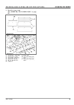
Page 52: ...es 2 Rubber plate 2 center 3 Upper plate 1 both sides 4 Upper plate 2 center 5 Short square neck bolt 6 Flange nut A Mower deck B Hole for installing upper plate 1 C Hole for installing upper plate 2 PREVENTING GRASS CLIPPINGS AND DUST FROM SCATTERING OPERATING THE MOWER ZD1211 ZD1221 49 ...

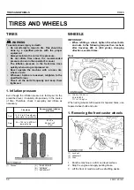
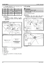
Page 53: ...wly in the course of time Therefore check it everyday and inflate as necessary Tire sizes Recommended inflation pressure Front 15 6 5 to 8 Smooth sem ipneumatic low profile tire Rear 26 12 0 to 16 4PR turf low profile tire 83 kPa 0 84 kgf cm2 12 psi 1 Ground A INSUFFICIENT B NORMAL C EXCESSIVE WHEELS IMPORTANT When refitting a wheel tighten the wheel bolts and nuts to the following torques then re...

Page 54: ...replacement wheel 2 Install the nylon sleeve with the wheel bolt and the lock nut 3 Tighten the nut IMPORTANT Insert the wheel bolt from the outside of the yoke Tighten the nut gradually until the wheel bearing play is eliminated and the wheel turns freely by hand Tightening torque 20 to 25 N m 14 8 to 18 4 lbf ft 2 to 2 5 kgf m 4 Lower the machine WHEELS TIRES AND WHEELS ZD1211 ZD1221 51 ...

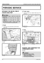
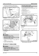
Page 55: ...od 1 To open the hood pull the latch lever frontward Lift the grip 1 Latch lever 2 Hood 3 Grip A RELEASE 1 Hood 2 Front cover 1 To open the front cover pull the bottom edge of the front cover 1 Front cover 3 Step 1 To open the step pull the grip 1 Step 2 Grip A PULL RAISING AND LOWERING THE OPERATOR S SEAT Raising WARNING To avoid serious injury or death Fully raise the operator s seat To the lock...

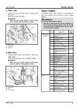
Page 56: ...the machine on a firm and level surface Set the mower deck height to 5 inch Stop the engine remove the key and engage the parking brake Be sure to chock the wheels Lock the raised axle with an L pin and snap pin before working under the machine 1 Lower the forward right anti scalp roller to the lowest position 2 Fully open the front cover 3 Unfold the tilt lever 4 Keep the front cover opened 5 Rem...

Page 57: ...key and apply the parking brake 1 Remove the screw of the lever guide 2 Pull up the lever guide How to install the lever guide 1 Install the lever guide 2 Tighten the screw IMPORTANT If the lever guide is out of alignment with the motion control lever move the lever guide to align it with the motion control lever 1 Lever guide 2 Screw 3 Screw LIFT UP POINT WARNING To avoid serious injury death or ...

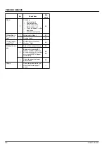
Page 58: ...e machine on a level surface with the engine shut off the key removed and the parking brake securely set or the rear wheels chocked No Check item Ref page Walking around the machine 1 Tire pressure wear and damage 50 61 2 Oil and water leak 3 Fuel level 59 4 Engine oil level 59 5 Transmission fluid level 60 6 Coolant level in the radiator and the recovery tank 60 7 Damage of machine body tightness...

Page 59: ...trol lever 87 2 Parking brake 71 Turning the key switch ON 1 Performance of the Easy checker light 29 Starting the en gine 1 Color of the exhaust fumes 29 2 Engine start system OPC system If either of these do not operate properly contact your local KUBOTA Dealer immediately 66 66 3 Check for abnormal noise and vibration 29 Others 1 Check the areas where pre vious trouble was experi enced PERIODIC...

Page 60: ... grease King pin 2 Until grease overflows Multipurpose EP2 Grease NLGI Grade No 2 Center pin 1 Front wheel 2 Rear mower link bushing 4 Front mower link bushing 2 Tilt lever 1 Universal joint 3 Seat adjuster 2 Parking brake lock pedal 1 Cable throttle 2 Moderate amount Oil MOWER Universal joint 3 Until grease overflows Multipurpose EP2 Grease NLGI Grade No 2 3 spindle shafts 3 Belt tension pulley 1...

Page 61: ...el Fuel used Engine oil classification API classification Oil class of engines except external EGR Oil class of engines with external EGR Ultra low sulfur fuel 0 0015 15 ppm CF CF 4 CG 4 CH 4 or CI 4 CF or CI 4 Class CF 4 CG 4 and CH 4 engine oils cannot be used on EGR type engines EGR Exhaust gas re circulation The CJ 4 engine oil is intended for diesel particulate filter DPF type engines and can...

Page 62: ...ill the fuel tank only to the bottom of the filler neck Check the fuel level Take care that the fuel tank does not become empty Fuel tank capacity 49 L 12 9 U S gals IMPORTANT Use diesel fuel only 1 Use No 2 diesel fuel 2 Use No 1 diesel fuel if the temperature is below 10 14 3 Always use a strainer when refueling to prevent fuel injection pump contamination IMPORTANT Do not permit dirt or trash o...

Page 63: ...very tank 3 When the coolant level drops due to evaporation add water only up to just below the fill port of the radiator and the full level of the recovery tank In case of leakage add antifreeze and water in the specified mixing ratio up to the full level See Flushing cooling system and changing coolant on page 80 4 Check radiator hoses for wear cracks bubbles or leaks If any such are found repai...

Page 64: ... the radiator screen and clean inside completely After cleaning replace the radiator screens properly 7 Check the radiator for dust or chaff build up If the dust or chaff has accumulated in the radiator clear with air pressure not to exceed 30 psi or a hose 1 Radiator screen 1 Hood screen 6 Checking the tire pressure WARNING To avoid serious injury or death Do not attempt to mount a tire on a rim ...

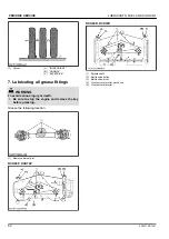
Page 65: ... sure to stop the engine and remove the key before greasing Grease the following location 1 Mower universal joint RCK60P RCK72P RCK60R RCK72R 1 Spindle shaft 2 Belt tension pulley 3 Belt tension pivot 4 Front anti scalp roller pivot boss 5 Front anti scalp roller PERIODIC SERVICE LUBRICANTS FUEL AND COOLANT 62 ZD1211 ZD1221 ...

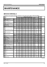
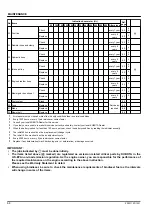
Page 66: ...ery 1000Hr or 1 year 79 2 8 Fuel filter element Check every 100Hr 70 Replace every 400Hr 79 3 9 Fan belt Adjust every 100Hr 71 10 Parking brake Adjust every 100Hr 71 4 11 Battery condition Check every 100Hr 73 5 12 Engine oil Change every 200Hr 76 6 13 Engine oil filter Replace every 200Hr 76 6 14 Transmission oil filter HST Replace every 200Hr 76 6 15 Front axle pivot Adjust every 200Hr 77 7 16 T...

Page 67: ... this service 4 If you feel you are unable to make this service correctly and safely contact your local KUBOTA Dealer 5 When the battery is used for less than 100 hours per year check the battery condition by reading the indicator annually 6 The initial 50 hours should not be a replacement change cycle 7 The initial 100 hours should not be an adjustment cycle 8 Every 2000 hours or every 2 years wh...

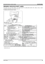
Page 68: ...s for your quick reference The label shows the recommended services from daily to every 4 years including fluid capacities tire pressure and so on For detail refer to operator s manual PERIODIC SERVICE CHART LABEL MAINTENANCE ZD1211 ZD1221 65 ...

Page 69: ... them inward from the NEUTRAL LOCK position to the NEUTRAL position and then release the levers 4 Turn the key switch to the START position 5 The engine must not crank Test 4 operator on the seat 1 Securely set the parking brake 2 Shift the PTO lever to the ENGAGE ON position 3 Set the motion control levers to the NEUTRAL LOCK position 4 Turn the key switch to the START position 5 The engine must ...

Page 70: ...BOTA Dealer to have the unit checked before operation 3 Checking gear box oil level WARNING To avoid serious injury or death Always stop the engine and remove the key before checking oil 1 Park the machine on a flat surface and lower the mower to the ground 2 To check the oil level loosen the oil inlet plug with gauge wipe it clean reinstall it and loosen it again See the following figures Check t...

Page 71: ...k plug 3 Oil inlet plug 4 Gear box 5 Check plug port 6 Rectangular label 7 Octagonal label A Oil level is acceptable within this range B Oil level 5 After checking reinstall the oil inlet plug with gauge securely 4 Greasing WARNING To avoid serious injury or death Be sure to stop the engine and remove the key before greasing Grease the following locations IMPORTANT Put grease into front wheel unti...

Page 72: ... avoid serious injury or death Be sure to stop engine and remove the key before cleaning air cleaner element 1 Remove the air cleaner cover and primary element 2 Clean the primary element When dry dust adheres to the element blow compressed air from the inside turning the element Pressure of compressed air must be under 205 kPa 2 1 kgf cm2 30 psi EVERY 50 HOURS MAINTENANCE ZD1211 ZD1221 69 ...

Page 73: ...element on page 79 Evacuator valve Open the evacuator valve once a week under ordinary conditions or daily when used in a dusty place to get rid of large particles of dust and dirt 2 Checking the fuel filter WARNING To avoid serious injury or death Be sure to stop the engine and remove the key when attempting to make the following checks and changes Never fail to check the fuel lines periodically ...

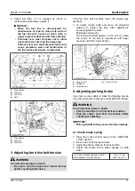
Page 74: ... the alternator outward to tighten the belt After adjustment securely tighten the bolts Moderate belt tension The belt must deflect approx 10 mm 0 4 in when the center of the belt is depressed with finger pressure of 98 N 10 kgf 22 lbs 1 Tension bolt 2 Alternator 3 Adjusting bolt A 10 mm 0 4 in 4 Adjusting parking brake If you feel you are unable to make the following service correctly and safely ...

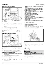
Page 75: ...f there is no play adjust the brake spring play again See Adjustment of brake spring play as follows 7 Adjust the other side spring to the same dimension Adjustment of brake spring play 1 Place the motion control lever to the NEUTRAL LOCK position 2 Be sure to chock the rear wheels 3 Release the parking brake completely 4 Loosen the lock nuts 5 Hold the brake rod by hand 6 Tighten the nut to the c...

Page 76: ...r eye protection and rubber gloves when working around the battery NOTE The factory installed battery is a non refillable type If the battery is weak charge the battery or replace it with a new one IMPORTANT Mishandling the battery shortens the service life and adds to maintenance costs The original battery is maintenance free but needs some servicing If the battery is weak the engine will be diff...

Page 77: ...tery it is necessary to recharge the battery as early as possible Failure to do this will shorten the battery s service life 3 When the specific gravity of electrolyte is between 1 27 and 1 29 the charging is completed 6 3 Storing the battery 1 When storing the machine for a long period remove the battery from machine adjust the electrolyte to the proper level and store in a dry place out of direc...

Page 78: ...60R RCK72R 1 Drain plug bolt 2 Check plug 3 Oil inlet plug 4 Gear box 5 Check plug port 6 Rectangular label 7 Octagonal label A Oil level is acceptable within this range B Oil level Label 6 7 Oil type Gear oil Gasoline engine oil Capacity 0 4 L 0 42 U S qts SAE SAE 90 SAE 10W 30 API Service Cat egory More than GL 3 SH or higher IMPORTANT Do not fill oil over the level to reach the check plug To pr...

Page 79: ...l down sufficiently Oil can be hot and may cause burns The oil filter must be changed every 200 service hours 1 Apply a slight coat of oil onto the rubber gasket of new filter 2 Tighten the filter quickly until it contacts the mounting surface Tighten filter by hand an additional 1 2 turn only 3 After the new filter has been replaced the engine oil level normally lowers a little Add engine oil to ...

Page 80: ...axle pivot pin adjustment is not correct vibration in the front wheel can occur Check and adjustment of the front axle end play 1 Lift up and securely block the front of the machine 2 Measure the clearance L between the front axle 4 and front axle support 3 3 If the measurement exceeds the allowable limit adjust the nut 1 1 Nut 2 Center pin 3 Front axle support 4 Front axle 5 Plain washer L Front ...

Page 81: ...for a few minutes stop it and check the oil level again add oil to the prescribed level IMPORTANT Operate only at low rpms immediately after changing the transmission fluid and filter Keep the engine at medium speed for a few minutes to insure proper lubrication of all parts so there is no damage to transmission 1 Drain plug 2 Hydraulic oil filter 1 Drain plug 2 Rear axle gear case LH 1 Oil level ...

Page 82: ...asket IMPORTANT To prevent serious damage or premature failure to the hydraulic system use only a KUBOTA genuine filter 3 Replacing fuel filter Consult your local KUBOTA Dealer for this service EVERY 800 HOURS 1 Adjusting engine valve clearance Consult your local KUBOTA Dealer for this service EVERY 1000 HOURS OR EVERY 1 YEAR Replace every 1000 hours or every 1 year whichever comes faster 1 Replac...

Page 83: ...diator drain plug and remove radiator cap See the figure The radiator cap must be removed to completely drain the coolant 3 After all coolant is drained close the drain valve and install the drain plug 4 Fill with clean water and cooling system cleaner 5 Follow directions of the cleaner instruction 6 After flushing fill with clean water and antifreeze until the coolant level is just below the fill...

Page 84: ... your local emergency number for further assistance When antifreeze comes in contact with the skin or clothing wash it off immediately Do not mix different types of antifreeze The mixture can produce chemical reaction causing harmful substances Antifreeze is extremely flammable and explosive under certain conditions Keep fire and children away from antifreeze When draining fluids from the engine p...

Page 85: ...very 2 years whichever comes faster NOTE The above data represent industry standards that necessitate a minimum glycol content in the concentrated antifreeze EVERY 3000 HOURS 1 Checking injection pump Consult your local KUBOTA Dealer for this service EVERY 1 YEAR 1 Checking fuel lines If you feel you are unable to make the following service correctly and safely contact your local KUBOTA Dealer See...

Page 86: ... worn or damaged replace or repair them at once 1 Hose 2 Clamp 5 Checking engine breather hose Consult your local KUBOTA Dealer for this service 6 Checking mower gear box oil seal Consult your local KUBOTA Dealer for this service EVERY 4 YEARS 1 Replacing hydraulic hoses Consult your local KUBOTA Dealer for this service 2 Replacing fuel lines Consult your local KUBOTA Dealer for this service 3 Rep...

Page 87: ...moved 1 When the fuel filter or lines are removed 2 When tank is completely empty 3 After the machine has not been used for a long period of time Bleeding procedure is as follows 1 Fill the fuel tank with fuel 2 Start the engine and run for about 30 seconds and then stop the engine 3 Checking and replacing blades WARNING To avoid serious injury or death Be sure to stop the engine and remove the ke...

Page 88: ... illustrated RCK60P RCK72P 1 Block A LOOSEN RCK60R RCK72R 1 Pipe A LOOSEN 3 To sharpen the blades yourself clamp the blade securely in a vise Use a large mill file and file along the original bevel until sharp 4 To check the blade for balance place a small rod through the center hole If the blade is not balanced file the heavy side of the blade until balance is achieved 5 Pass the spline boss thro...

Page 89: ...e the mower deck from the machine See DISMOUNTING THE MOWER DECK on page 25 2 Remove the left and right hand shield from the mower deck 3 Clean around the gear box 4 Remove the belt from the tension pulley 5 Remove the right hand bracket which mounts the gear box to the mower deck and slip the belt over the top of the gear box 6 To install a new belt reverse the previous procedure NOTE Tighten bra...

Page 90: ...trol levers can be adjusted independently 1 HST neutral 1 Lift up and secure with jack stands or by blocking the rear of the machine frame 2 Remove both rear wheels 3 Set the engine speed to maximum 4 Place the motion control lever in the NEUTRAL LOCK position 5 After forward and backward operation tighten the guide control at the position when wheel axis stops 6 Adjust the rod length L of the dam...

Page 91: ... right and left 1 Loosen the nut 2 Slide both levers forward or rearward to the desired position within tab slots until the levers are aligned 3 Tighten the nut NOTE If the ends of the levers strike against each other while in the NEUTRAL position move the levers outward to the NEUTRAL LOCK position and carefully bend them outward Move them back to the NEUTRAL position and check for the recommende...

Page 92: ...emove the key and remove the mower universal joint while checking or adjusting the level of the mower deck IMPORTANT Check the machine tire pressure Inflate the tires to the correct pressure See TIRES AND WHEELS on page 50 Checking the level side to side NOTE The mower deck anti scalp rollers should not contact the ground RCK60P RCK72P 1 Raise the mower deck to the top position 2 Turn the cutting ...

Page 93: ...right side of the machine 7 Adjust the cutting height fine tuning bolts to set 76 mm 3 in blade height Front and rear side bolts must be adjusted 8 Lock the nuts 9 Adjust the left side equally 10 Check the side to side level If it is not level adjustment is necessary 1 Cutting height fine tuning bolt 2 Lock nut 3 Leveling the mower deck front to rear WARNING To avoid serious injury or death Park t...

Page 94: ...height set dial to the 3 in cutting height position 3 Place 51 mm 2 in height wood blocks under each side of the mower deck Anti scalp rollers must not rest on the wood block 4 Lower the mower deck 5 Loosen the lock nuts of the front side of the machine 6 Adjust the cutting height fine tuning bolts to set 76 mm 3 in blade height Both front side bolts must be adjusted 7 Lock the nuts 8 Adjust the o...

Page 95: ...2 47 5 57 0 4 84 5 82 45 54 61 0 73 2 6 22 7 47 M10 lbf ft N m kgf m 35 5 41 2 48 1 55 8 4 9 5 7 44 9 52 1 60 8 70 5 6 2 7 2 1 2 lbf ft N m kgf m 80 96 108 5 130 2 11 07 13 29 110 132 149 2 179 0 15 22 18 27 M12 lbf ft N m kgf m 57 2 66 5 77 5 90 1 7 9 9 2 76 0 86 8 103 117 10 5 12 0 9 16 lbf ft N m kgf m 110 132 149 2 179 0 15 22 18 27 160 192 217 0 260 4 22 14 26 57 M14 lbf ft N m kgf m 91 2 108...

Page 96: ... 2 38 3 2 9 48 1 55 9 52 0 3 9 4 9 5 7 5 3 0 4 M12 17 or 19 46 3 53 5 49 9 3 6 62 8 72 6 67 7 4 9 6 4 7 4 6 9 0 5 57 1 66 5 61 8 4 7 77 6 90 2 83 9 6 3 8 0 9 2 8 6 0 6 M14 19 or 22 79 6 92 6 86 1 6 5 107 9 125 5 116 7 8 8 11 0 12 8 11 9 0 9 91 1 108 5 99 8 8 7 123 6 147 0 135 3 11 7 12 6 15 0 13 8 1 2 NOTE Figure 7 on the top of the bolt indicates that the bolt is made of special material Before t...

Page 97: ... with the negative terminal first When connecting the cables to the battery start with the positive terminal first See Storing the battery on page 74 8 Keep the machine in a dry place where the machine is sheltered from rain Cover the machine 9 Store the machine indoors in a dry area that is protected from sunlight and excessive heat If the machine must be stored outdoors cover it with a waterproo...

Page 98: ...the control levers in the neutral lock position and let the engine idle for at least 5 minutes 10 Shut the engine off and walk around machine and make a visual inspection looking for evidence of oil or water leaks 11 With the engine fully warmed up release the parking brake and test the brakes for proper adjustment as you move forward Adjust the brakes as necessary STORAGE ZD1211 ZD1221 95 ...

Page 99: ...ent or dirty fuel Check the fuel valve position Check the fuel system Air cleaner clogged Clean the element The engine stops suddenly Insufficient fuel Check the fuel valve position Refuel Bleed the fuel system if necessary Exhaust fumes are colored Black Fuel quality is poor Too much oil Engine is overloaded Change the fuel and fuel filter Check the proper amount of oil Reduce engine load Blue wh...

Page 100: ...ndicates the location of the trouble If an error code appears immediately contact your local KUBOTA Dealer for repairs 1 Master system warning indicator 2 Error code Displayed error code Trouble Operator s action Err 1 Water temperature sensor trouble Contact your local KUBOTA Dealer Err 2 Fuel sensor trouble Err 3 Meter panel memory reading trouble POWER TRAIN TROUBLE SHOOTING TROUBLESHOOTING ZD1...

Page 101: ...e top of the plates look whitish The battery was used with an insufficient amount of electrolyte Add distilled water and charge the bat tery Regularly check the electrolyte lev el The battery was used too much without re charging Charge the battery sufficiently Charge the battery properly Recharging is impossible The battery life has expired Replace the battery Terminals are severely corroded and ...

Page 102: ... age adjustment or pressure adjustment The control linkage pivots are sticking Pull up and lubricate linkage Fuel decreases uneven in LH and RH tanks Fuel filter is clogged Replace fuel filter Fuel valve is closed Open the fuel valve Check valve is clogged Replace check valve Bypass hose kink in the pipe between LH and RH tanks Remove the kink or replace the pipe Master system warning indicator fl...

Page 103: ... on page 50 Blades scalping grass Cutting height too low Raise the cutting height Turning speed too fast Reduce speed on turns Ridges in terrain Change the mowing pattern Rough or uneven terrain Adjust wheels pressure and anti scalp rollers Anti scalp rollers not adjusted correctly Adjust wheels pressure and anti scalp rollers Bent blade s Replace blade s Mower belt slipping Mower deck plugged Unp...

Page 104: ... warning information 61 refueling 59 daily check list 55 dust preventing from scattering 48 E Easy Checker indicators 29 engine jump starting 33 operating warning information 27 starting 27 starting in cold weather 32 starting information 29 stopping 29 stopping immediately 29 troubleshooting 96 warming up 32 33 engine break in 34 engine breather hose checking 83 replacing 83 engine oil changing 7...

Page 105: ...ing procedure 18 servicing 8 17 specification table 19 starting 36 47 starting to operate 6 stopping 8 41 storing 11 94 tilting up 53 transporting 8 43 troubleshooting 99 warranty 18 working 6 machine new changing engine oil 34 changing lubricating oil 34 changing oil filter cartridge 34 changing transaxle fluid 34 operating 34 operating warning 34 motion control lever 39 adjusting warning informa...

Page 106: ... general information 5 operating on slopes 7 ROPS 6 servicing the machine 8 starting to operate the machine 6 stopping the machine 8 storing the machine 11 transporting the machine 8 using the lift link 8 working the machine 6 safety for children 7 safety for operators age 60 years and older 7 safety labels 12 care 16 seat belt 37 service code display 31 service intervals 63 skid installation 25 r...

Reviews: