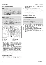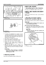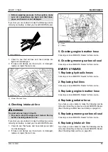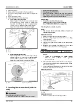
1. Change the rear side of the damper to the desired
hole location.
Tighten the rear side damper nut.
(1) Damper
(2) Damper nut
(F) Front
(H1) Hole for lighter setting
(H2) Hole for heavier setting
4. Motion control lever alignment
WARNING
To avoid serious injury or death:
• Park the machine on a firm and level surface.
• Stop the engine, remove the key and apply the
parking brake.
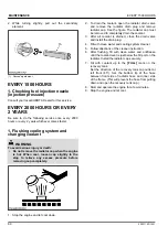
4.1 Checking the alignment
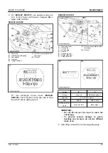
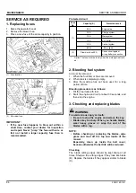
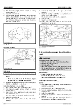
1. Check the gap and space between the levers at the
maximum forward position.
Recommended gap:
0 to 4 mm (0 to 0.16 in.)
If the positions of the motion control levers are
unequal, adjustment is necessary.
(A) “GAP”
4.2 Aligning the motion control levers
1. Stop the engine and apply the parking brake.
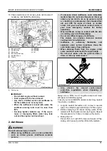
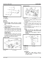
Lever position (high or low)
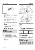
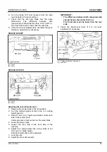
1. Remove the nut and select the motion control lever
position, high or low.
2. Tighten the nut.
(1) Motion control lever
(2) Bolt
(3) Nut, washer
Lever alignment (right and left)
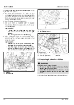
1. Loosen the nut.
2. Slide both levers forward or rearward to the desired
position within tab slots until the levers are aligned.
3. Tighten the nut.
NOTE :
• If the ends of the levers strike against each
other while in the “NEUTRAL” position, move
the levers outward to the “NEUTRAL LOCK”
position and carefully bend them outward.
Move them back to the “NEUTRAL” position
and check for the recommended space.
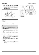
MOWER DECK LEVEL
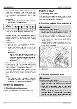
1. Anti-scalp rollers
WARNING
To avoid serious injury or death:
• Park the machine on a firm and level surface.
• Apply the parking brake.
• Stop the engine and remove the key.
• Wait for all moving parts to stop.
NOTE :
• The flattest cut can be achieved by having the
anti-scalp rollers adjusted off the ground.
Check the anti-scalp roller adjustments each
time the mower deck cutting height is changed.
It is recommended that all the anti-scalp rollers
be kept off the ground to minimize scuffing.
1. Check the machine tire pressure.
Inflate tires to the correct pressure.
(See TIRES AND WHEELS on page 50.)
ADJUSTMENT
MOTION CONTROL LEVER
88
ZD1211,ZD1221

