background image


Kudo3D Titan 1 - Build Manual 

Ver. 1.1


26

 of 

33 

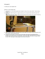
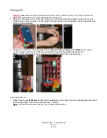
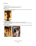
Connecting to the Linear Stage


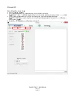
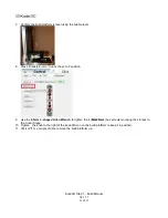
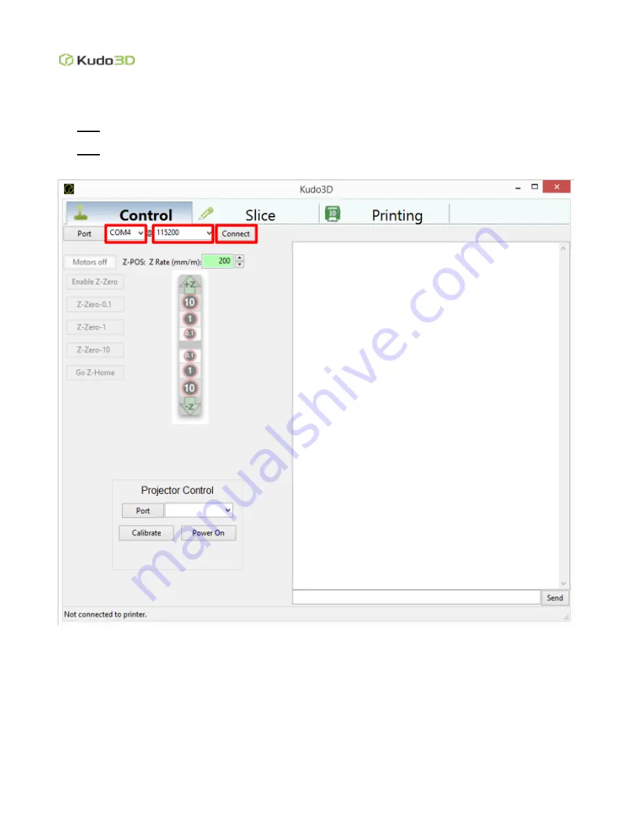
3.  Run the Kudo3D software. 
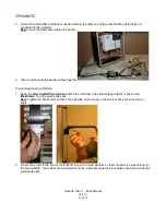
4.  Plug in the black USB cable to the computer you would like to print from. 

Note

: Most Windows 7 and 8 are plug and play. For some cases, additional drivers will need to be installed. 

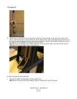
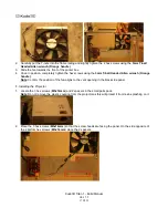
5.  After plugging in the USB cable from the circuit board, the computer will assign it a COM#. 

Note

: The COM# is a unique number for your circuit board. Please keep this same USB plug to the same 

port on the computer. 
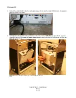
6. 

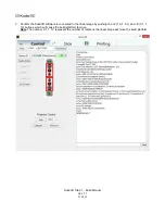
Select the 115200 baud rate and then press “Connect.” 


Summary of Contents for Titan 1

Page 1: ...Build Manual Titan 1 Ruby Diamond Editions Revision 1 1 ...

Page 2: ...is material may be distributed only subject to the terms and conditions set forth in the Creative Commons Attribution NonCommercial NoDerivatives 4 0 International License or later The latest version is presently available at http creativecommons org licenses by nc nd 4 0 ...

Page 3: ... A Installing the Linear Stage Module 12 Installing the Linear Stage Module 12 B Attaching the Metal Structural Plate 13 C Installing the Circuit Board 15 E Mounting the Fan 16 F Installing the Projector 17 G Plugging in the Cables 19 H Attaching the Build Platform 21 III Installing the Resin Container 23 III Leveling the Printer 24 IV Installing the Kudo3D Software 25 V Calibrating the Build Plat...

Page 4: ...Kudo3D Titan 1 Build Manual Ver 1 1 4 of 33 I Standard Package Materials and Tools 1 Printer frame and panels 2 Upper Foam 2 1 Z Axis Linear stage actuator assembly ...

Page 5: ...age Module 2 1 1 1 Stepper Motor 2 1 1 2 Flexible Motor Coupler 2 2 Circuit Assembly Rachel Uchitel 2 2 1 Mega 2560 Controller 2 2 2 RAMPS 1 4 Board 2 2 3 A4988 Driver Chip 2 3 Build platform 2 4 L Bracket for securing build platform to the linear stage module ...

Page 6: ...Kudo3D Titan 1 Build Manual Ver 1 1 6 of 33 2 5 Hand Screw w Black Plastic Head for securing build platform 2 6 Lens Duster starter kit 2 7 Dust Blower starter kit 3 Starter Kit ...

Page 7: ... 1 Cover Ruby Version Ruby Red Acrylic sheets 5 Pieces Total Diamond Version Diamond Neon Orange Acrylic sheets 7 Pieces Total 3 2 3mm Double sided tape this is for bonding the acrylic sheets to make the cover 3 3 12cm Fan 3 4 Silicone Funnel starter kit ...

Page 8: ... connecting power to the projector 3 6 12V DC Adapter this is for providing power to the circuit assembly 3 7 Calibration Ruler starter kit Please trim the sheet to 11 5cm x 20cm 3 8 Stainless Steel Plate for supporting linear stage module 3 9 Leveling feet 4 used to level the printer ...

Page 9: ... 3 9 3 USB to RS 232 Cable blue connector 3 9 4 RS 232 Cable white color 3 9 5 Wood Handled Spatula starter kit 3 9 6 Wire Cutters starter kit 3 9 7 Triangular Level starter kit 3 9 8 Blades for removing printed models in brown paper starter kit 3 9 9 2mm Slotted Screw Driver 3 9 10 Back up Panel Snap on Clips x2 ...

Page 10: ...k 3 10 1 1 5mm L shaped Allen Wrench Not provided with the other tools 3 10 2 2 5mm L shaped Allen Wrench 3 10 3 M3x14mm Screws x3 3 10 4 M3 Spacers x2 3 10 5 M4x20mm Screws x4 3 10 6 M5x6mm Screws x10 3 10 7 M5 T Nuts x10 3 10 8 Lens Stop starter kit 4 Projector 4 1 DLP 3D Projector Wrapped in protective plastic 4 2 Power Cable 4 3 VGA Cable not used ...

Page 11: ...face 2 Remove all of the panels from the printer frame a Remove the front panel first then remove the side panels 3 Roll the nuts to the bottom of each leveling foot 4 Place the printer frame upside down and screw in the 4 leveling feet to the bottom of the printer case 5 Place the printer frame right side up ...

Page 12: ...g the back of the printer to ensure the cable is fully through the opening 3 Rotate the linear stage back to the upright position with the black cover facing the front of the printer and the 2040 aluminum extrusion facing the back 4 Carefully slide in the stepper motor and lower the linear stage until the bottom of the 2040 aluminum extrusion is at the same level as the top steel plate Push the li...

Page 13: ...ually with the screws fixed towards the outside of the brackets towards the edge of the brackets Do not tighten one screw all the way at a time Note Make sure the brackets do not extend pass the back of the printer Make sure the brackets are well tightened so the linear stage module is secured firmly B Attaching the Metal Structural Plate 1 Remove the plastic film protecting the steel support plat...

Page 14: ... place the steel support plate with the T nuts facing forward into the slots of the back of the printer box frame Using the 3mm T ball Headed Allen wrench Orange handle tighten the 8 hex screws one by one Note The steel support plate should be flush with the linear stage and the printer box Make sure after tightening the T nuts are perpendicular to the slots If a T nut is stuck in the slots loosen...

Page 15: ...osen Do not completely unscrew the 4 hex screws 3mm holding up the circuit board mounting plate raise it past the midpoint of the printer box and tighten the screws again 2 Locate the aluminum heat sink in the anti static circuit board parts pack and carefully place the heat sink over the small black chip of the red A4988 driver board ...

Page 16: ...nting plate Tighten the plastic nuts to mount the circuit board 4 Connect the cable from the linear stage with the Red wire UP and Yellow wire DOWN to the vertical column of pins in the Z section of the red circuit board closest to the A4988 chip Heat sink Note Confirm the cable from the linear stage is plugged in correctly to prevent damage E Mounting the Fan 1 Place 2 hex screws M5x6mm so that t...

Page 17: ... the 3mm T ball Headed Allen wrench Orange handle Note Confirm the position of the fan aligns to the vent opening in the black side panel F Installing the Projector 1 Locate the 3 hex screws M3x14mm and 2 spacers in the small parts pack Note Do not remove the plastic covering from the projector as this will protect it from resin splashing on it 2 Place the 3 hex screws M3x14mm so that the screw he...

Page 18: ...to the projector before mounting it into place 4 Carefully place the projector in the printer box so the 3 hex screws M3x14mm align with the projector mountings and use the 2 5mm L shaped Allen Wrench to screw the projector into position Do Not over tighten the hex screws Note Make sure the hex screws are in the middle of the slot ...

Page 19: ...the life of the resin container WARNING DO NOT use paper or plastic to cover the project lens as it might burn or melt G Plugging in the Cables 1 Unwrap the tie wrap from the fan cable Note Make sure the cable goes underneath the projector 2 Use the 2mm Slotted Screw Driver to loosen the D9 Negative the D9 Positive and plugin the two wires to the bottom of the circuit board and tighten the 2 termi...

Page 20: ... with the projector Slide the green connector through the hole at the back of the printer case and attach the adapter to the 5Amp connector of the RAMPS 1 4 circuit board 4 Connect the larger end of the USB cable to the Mega 2560 circuit board and pass the other end flat through the big hole on the back panel ...

Page 21: ...latform 1 Using the 2mm Slotted Screw Driver attach the L bracket to the linear stage with the 4 hex screws M4x20mm from the small parts pack Note Tighten the hex screws so that it can still slide up and down in the slot but does not tilt over at an angle 2 Loosen the screw to the right of the Kudo3D logo on the build platform so that connector is perpendicular to the build platform then attach th...

Page 22: ...te Make sure the Kudo3D logo faces the front of the printer Use the hand screw to coarse level the build platform with the bubble level on top of the build platform 3 Clean the bottom of the build platform using dust free cloth IPA Isopropyl Alcohol ...

Page 23: ...ide or the bottom of the container 1 Using the 3mm T ball Headed Allen wrench Orange handle loosen the screws on the resin container bar Do Not completely unscrew and put the side of the resin container that has a bottom edge below the resin container bar Note Make sure the resin container is flush with the bar and pushed all the way up to the hex screw head on the front left of the printer box 2 ...

Page 24: ...ur leveling feet to make sure the two bubbles are in the middle Leveling the Resin Container 3 Carefully place the bubble level in the resin container to confirm that it is still level Note The surface of the resin container is very delicate Do not scratch the surface Use the brush or dust blower to remove particulates Leveling the Projector 4 Place the bubble level on top of the projector to conf...

Page 25: ...g the Kudo3D Software Powering Up the Linear Stage 1 Plug in the power cable connected to the AC DC adapter from the circuit board Note Installing the Kudo3D Software 2 Run the Kudo3D installer and follow the instructions on the installation wizard a d b e c ...

Page 26: ... from Note Most Windows 7 and 8 are plug and play For some cases additional drivers will need to be installed 5 After plugging in the USB cable from the circuit board the computer will assign it a COM Note The COM is a unique number for your circuit board Please keep this same USB plug to the same port on the computer 6 Select the 115200 baud rate and then press Connect ...

Page 27: ...rm the Kudo3D software is connected to the linear stage by pushing the Z 10 1 0 1 and Z 0 1 1 10 buttons which will cause the build platform to move Note The number 0 1 1 10 represent the number of rotations the linear stage will move the build platform ...

Page 28: ...when establishing the Z zero position because once the build platform makes contact with the bottom of the resin container it will push the L bracket up which will cause the hex screw heads to move down in relation to their respective slots Additionally loosen the knob to the right of the Kudo3D icon on the build platform so that when it makes contact with the resin container it will be level in r...

Page 29: ...Disable Z zero to lock the zero Z position 9 Use the 2 5mm L shaped Allen Wrench to tighten the 4 M4x20mm hex screws mounting the L brack to the Linear Stage 10 Tighten the knob to the right of the Kudo3D icon on the build platform to keep it in position 11 Click Z 10 a couple of time to move the build platform up ...

Page 30: ...e Plug in the black HDMI cable to your computer Plug in the blue USB cable from the USB to RS232 conversion cable to your computer 3 On the connected computer go to Control Panel Appearance and Personalization Display Screen Resolution 4 Confirm that the projector s resolution is 1920 x 1080 set Multiple Displays to Extend these displays and click the Apply button 5 Under the Control tab under the...

Page 31: ...d that users set their desktop background to black 6 Under the Control tab under the Projector Control section in the Kudo3D software click Calibrate and a red grid will appear under the resin container 7 Set the zoom to the center and adjust the focus of the projector lens so that the red grid is as clear as possible 8 Play with the focus and the projector to get the best result 9 If necessary us...

Page 32: ... after being cut into a 20 cm by 11 cm grid Size calibration can be performed with a coarse focusing on the ruler To calibrate the size tighten only one screw on one end of the projector supporting steel plate with the orange wrench provided Put the bubble level on top of the projector and move the other end of the steel plate to level the projector Then tighten one screw on the other end now Chec...

Page 33: ...ctly at the projector lens Adjust the focus of the grid lines as clear and uniform as possible in the central region You will not get a nice focus for the four corners because of the spherical aberration of the lens module After reaching a nice focus please insert the lens stop provided Make sure the focus maintains after the lens stop is inserted If the lens does not extend all the way close to t...

Reviews: