-9-
SAFETY GUARDS
The safety guards protect against accidents and therefore ensure maximum machine
safety. EL 100 N for Great Britain are equipped with special guards (see page 23).
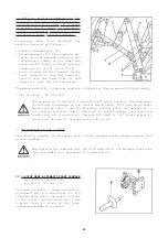
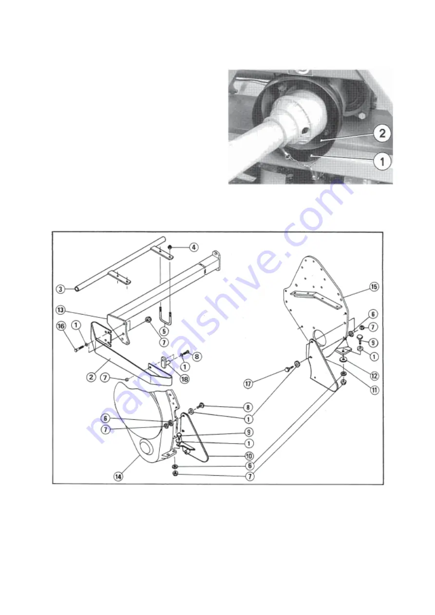
Fit the guard extension (1) over the
sheet metal guard (2) of the torque
limiter (see photo opposite).
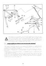
Bolt both front guards (3) to the front support tube (13) ensuring that their ends
are kept as close as possible to outside of the machine.
Bolt deflectors (2, 10 and 11) respectively to front support tube (13), side gear
casing (14) and side plate (15) as shown on assembly diagram below.
1 = Thrust washer 13 x 24 x 3,2 9 =
Hexagon bolt M12x50
4 = Self locking nut M 10
16
=
Hexagon bolt M12x65 on housing side (14)
5 = U-bolt
Hexagon bolt M12x55 on plate side (15)
6 = Spring washer M 12
17
= Hexagon bolt M12x30
7 = Hexagon nut M 12
18
=
Spacer
8 = Hexagon bolt M12x35
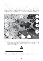
Note : When fitting the machine with either a crumbler or a packer roller, first remove
the side guard (2). As position of the roller support arms conforms to safety
regulation, this side guard is no longer necessary and must be removed to avoid
interference.
Summary of Contents for EL 100 N
Page 1: ...ASSEMBLY OPERATOR S MANUAL EL 100 N POWER TILLER N 95458 A GB 12 1999...
Page 10: ...8...
Page 18: ...16...


