-21-
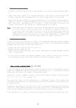
b) Adjusting scraper plates
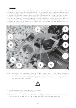
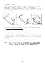
- Slightly loosen fixing bolts (V) of the scrapers (P) so that they slide freely (photo
1).
- Check that their position is central relative to the rows of roller teeth. The
scraper supports have elongated holes to allow readjustment if necessary.
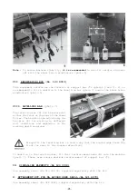
- After having checked that the scraper assembly is in its furthest forward position
(photo 2), position scraper plates one at a time so that they are all in contact
with the roller. Retighten bolts (V) (photo 1). Make sure that the plates only
lightly touch the roller and do not interfere with its rotation.
Note : When operating in difficult conditions, before adjusting the scrapers (D),
it can be useful to deflect the roller to simulate its working position.
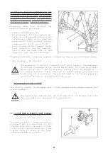
To do this, lower the Power Tiller onto a block of wood positioned under the
packer roller at its centre. The roller is now slightly deflected as it may
sometimes be found in very difficult conditions. Adjustment of scrapers (P)
can now be carried out as described before for normal conditions.
c) Cleaning the scrapers
In case of crop or soil build-up, to clean, it is recommended that the scraper assembly
is pivoted to the rear around the two upper bolts (R) (one on left-hand side of scraper
assembly and the other on the right) (photo 1).
- Loosen the self-locking nuts (S) (photo 2).
- Release the two eyebolts (Q).
- Remove the two lower bolts (R) (one on left-hand side of scraper assembly and the
other on the right).
- To facilitate pivoting the scraper assembly, use a lever in each of the two holes
(L) situated at each end of the connecting tube (H) (photos 1 and 2).
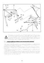
II. REAR 3-POINT LINKAGE FRAME (No 120 7280)
A 3-point linkage can be supplied as an optional extra so that it is possible to attach
additional implements such as seed drills, broadcasters, etc. to increase the working
efficiency and reduce the number of separate passes.
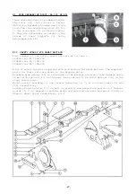
Chassis (3) of rear linkage is fitted on the 3-point frame of the EL 100 N using parts
(10 - 11 - 12 - 13 - 14) and axis (2).
The lower link arms (19) are adjustable in 3 different lengths. This enables the
overhang of the combination to be reduced by attaching the machine as near as possible
to the EL 100 N.
The height adjustment of the lower links (19) is achieved through the two tensioning
chains (6). This distance between both lower links (19) is determined by the bent
tube (23) by changing the position of the 4 butting rings (22) laterally.
The stretchers (21) of both crossed chains laterally stabilize the lower links (19).
Summary of Contents for EL 100 N
Page 1: ...ASSEMBLY OPERATOR S MANUAL EL 100 N POWER TILLER N 95458 A GB 12 1999...
Page 10: ...8...
Page 18: ...16...


