-28-
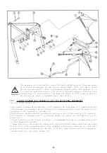
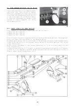
3 = hexagon screw (M10 x 20) 17 = self locking nut (M16)
4 = self locking nut (M10) 18 = hexagon screw (M16 x 35)
11 = hexagon screw (M12 x 60) 20 = hexagon screw (M12 x 25)
12 = hexagon screw (M12 x 45) 21 = self locking nut (M12)
15 = hexagon screw (M16 x 60)
XIII) NYLON CLEANING PLATES FOR PACKER ROLLER SCRAPERS
Part No. 525 702 00
These cleaning plates are made from a supple synthetic material which enables them to
be slightly pre compressed against the roller for improved cleaning action.
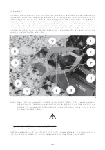
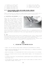
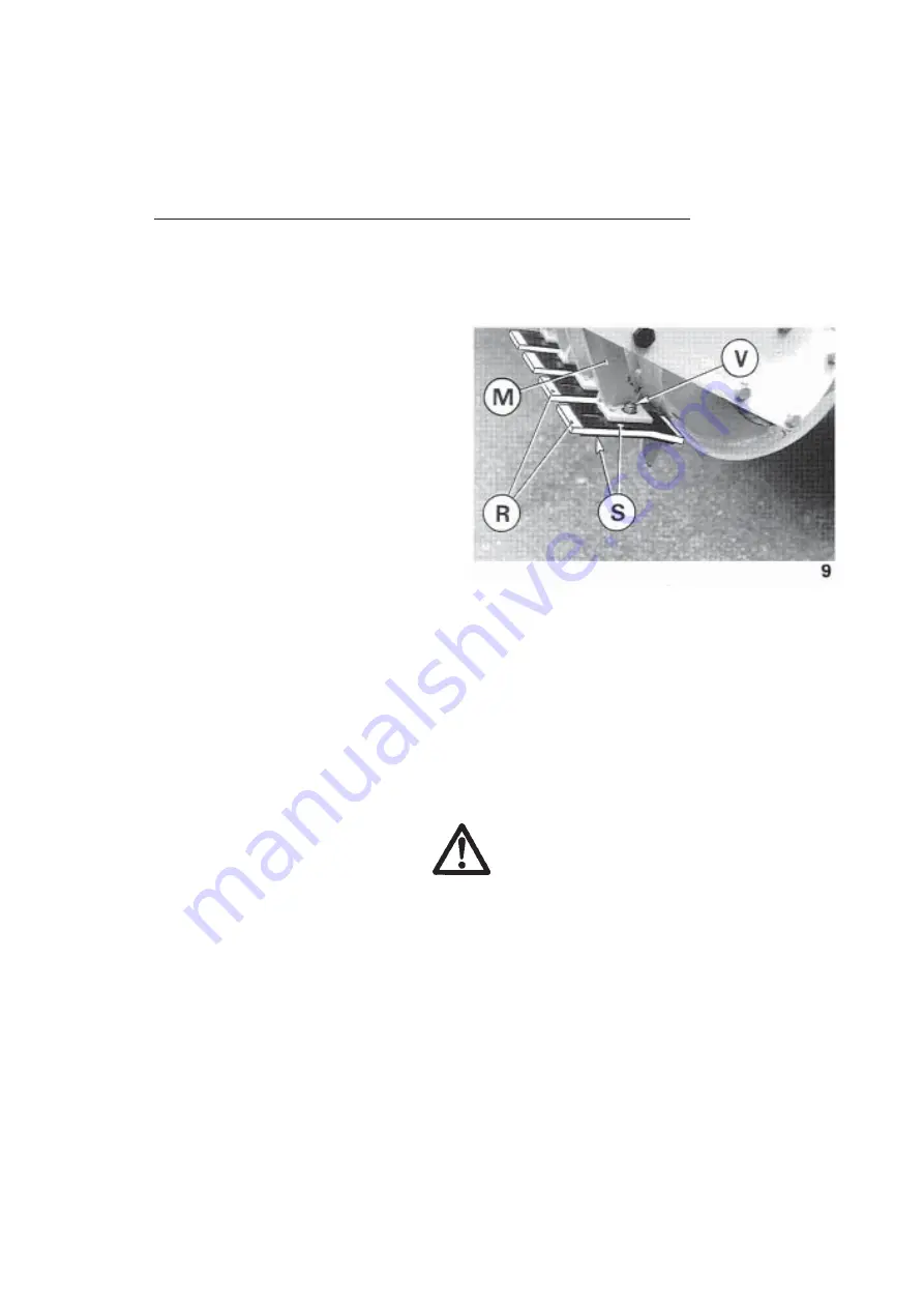
a) Installation and adjustment (photo 9)
Place the nylon cleaning plate (part
number 525 702 00) between two new and
unused steel scraper plates (S) (part
number 525 321 30) acting as carrier
plates. Bolt this assembly onto the
laterally adjustable scraper supports
(M) with one cup square bolt (V) (M10 x
35 -part number 500 073 00) and its nut.
Allow the nylon cleaning plate to stick
out of the carrier plates by 10 mm and
press it slightly against the roller so
that its leading edge is in contact with
the roller segment across its full width.
Rotate the roller one complete turn to check that there is no gap between roller and
nylon cleaning plate. Re-adjust the plate if this is not the case. Also check that the
upper carrier plate is set parallel to the roller segment and does not come into contact
with it.
b) Use :
The nylon cleaning plate is particularly recommended for light, loamy or chalky grounds
with little crop residue or stones. A correct cleaning plate adjustment results in a
clean and shiny roller area across the full width of the cleaning plates.
Soil deposit on the roller will result in premature cleaning plate wear. Readjust them
quickly. The cleaning plate is reversible for increased service life.
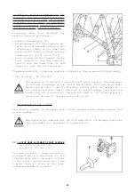
F. IMPORTANT RECOMMENDATIONS
- ALWAYS STOP THE TRACTOR ENGINE BEFORE CARRYING OUT MAINTENANCE OR CLEANING.
- BEFORE PUTTING THE MACHINE INTO THE GROUND, ENSURE THAT IT IS OPERATING AT WORKING
SPEED
(ROTATIONAL FREQUENCY).
- WHEN STOPPING WORK, LIFT THE MACHINE OUT OF THE TILTH WHILE ROTOR IS STILL TURNING.
- WORK IN A STRAIGHT LINE IF POSSIBLE. WHEN TURNING CORNERS, LIFT THE MACHINE OUT
OF WORK.
- IN CERTAIN CONDITIONS, IT MAY BE NECESSARY TO MAKE SEVERAL PASSES IN ORDER TO ACHIEVE
THE DESIRED TILTH.
- IF THE ANGLE OF THE UNIVERSAL JOINTS ON THE PTO SHAFT EXCEEDS 40° WHEN LIFTED ON
THE TRACTOR LINKAGE, STOP THE PTO.
Summary of Contents for EL 100 N
Page 1: ...ASSEMBLY OPERATOR S MANUAL EL 100 N POWER TILLER N 95458 A GB 12 1999...
Page 10: ...8...
Page 18: ...16...


