background image

    Operating instructions  KEA 202 INS         - 

11 / 22

 -     File: 

BA_KEA 202 INS_EN_Ver 2016-07-01.docx


______________________________________________________________________________________ 

Alfred Kuhse GmbH 

Telefon: +49 4171-798-0 

kuhse@kuhse.de 

Technische Änderungen vorbehalten 

An der Kleinbahn 39, D-21423 Winsen (Luhe) 

Telefax: +49 4171-798-117 

www.kuhse.de 


10. 

Alarm messages 

The automatic system can process 64 alarms. Alarms 1 - 19 and 49 

– 64 are variable from the text and from 

the resolution, i.e. the texts and control of these alarms were specified with the P

ARA

W

IN

 parameterisation 

program. They are controlled by contact inputs (connections 1 to 14 unused inputs of the additional relay 
unit) or by internal flags (controller impeded, analogue channel limit value too high, etc.). The parameterisa-
tion is described in the service manual. Because of the parameterisation, deviations from the following de-
scription can exist. 
The alarms are basically divided into three groups: 

  Alarms that are only monitored delayed after start-up of the motor (e.g. low oil pressure). The release can 

be recognised on the green 'monitoring On' display. 

  Alarms that are also monitored when the motor stops (e.g. battery undervoltage), except in the Off operat-

ing mode. They are designated as 

without delay

  The alarm messages 13 and 14 are always monitored, even in the Off operating mode.


They are used for 

messages (e.g. leaks). The horn is not switched on in the Off operating mode, but the alarms are not in-
cluded in the collective alarm. They behave like normal alarms if an active operating mode (so not Off) is 
selected. 


The alarms are configured as follows: 

  Alarm is active or locked 

  Contact is in standby current or operating current, 

  Delayed or undelayed monitoring 

  Warning or switching-off function 

  In addition for warning alarms: With or without generator switch-off and with Stop after run-on time gener-

ator switch-off in automatic operation. 


If the generator is switched off due to a warning alarm in automatic operation, the engine is stopped after the 

idle time and the automatic system is locked. 


For  contact  inputs,  the  respective  alarm  is  triggered  with  the  closing  (operating  current  circuit)  or  with  the 
opening (standby current circuit) of the signal contact against negative potential, and for analogue signals, with 
the exceeding or falling below of the set limit values. Alarms 11 to 14 can also be parametrised as a failsafe 
signal on output relays, i.e. the respective relay attracts if the alarm is not pending. 


Summary of Contents for KEA 202 INS

Page 1: ...ions and fastenings as its predecessor replacement is simple Four dedicated operating messages and four programmable operating displays can be labelled by replaceable paper strips and are indicated by...

Page 2: ...missioning 4 5 3 Connections 4 5 4 Battery and supply voltage 4 5 5 Coils 4 6 Basic operation of automatic system 5 6 1 Operation of the display 5 6 2 Display contrast setting 5 6 3 Parameterisation 6...

Page 3: ...monitor 13 10 2 11 Monitoring the flows 13 10 2 12 Maintenance interval reached 13 10 2 13 Maintenance interval exceeded 13 11 Actual values 14 11 1 Description 14 12 Further functions 15 12 1 Freque...

Page 4: ...ions especially those of the VDE must be observed 2 The information in the service instructions must be complied with prior to commissioning 3 The parameterisation of the unit must be carried out in s...

Page 5: ...key and pressing the key the ACTUAL VALUES group is directly selected by holding LED TEST and pressing the key the display of alarms is directly selected To change a parameter first enter the valid I...

Page 6: ...dent and PIN numbers Parameterisation is described in the Service Manual You do not need to enter a valid Ident number to modify parameters of this group Duration of display illumination The backgroun...

Page 7: ...reen display after the genset start up signals the release of the operating dependent delayed alarms As soon as the motor has started up this display flashes until the monitoring is enabled The displa...

Page 8: ...if the measuring voltage is connected with a left rotation field or if the volt age has too large an asymmetry of the vectors If an enabled monitoring signals a deviation from the nominal range the r...

Page 9: ...the negative potential as otherwise no start is carried out 8 2 Off operating mode The Off position is automatically selected reset function during the application of battery voltage in order to preve...

Page 10: ...after the start function is enabled If the generator voltage with its voltage and frequency values are within the nominal ranges generator operation can be switched on using the GEN ON I key resp swi...

Page 11: ...ed when the motor stops e g battery undervoltage except in the Off operat ing mode They are designated as without delay The alarm messages 13 and 14 are always monitored even in the Off operating mode...

Page 12: ...If no alarms are pending the note No alarms present is displayed when opening the pages 10 2 Description of the alarms 10 2 1 Engine does not switch off If the running message of the motor is still pe...

Page 13: ...l coupling switch can be switched off via an output to be parametrised 10 2 10 Alarms of the voltage monitor The frequency and voltage deviations of the generator can be displayed as error messages An...

Page 14: ...3 ASYMMETRIC LOAD Power load of the generator for THERMAL OVERLOAD ALARM Maximum asymmetric load of the three generator flows 7 BATTERY 26 6 V VOLTAGE Display of the battery voltage The measuring sig...

Page 15: ...are counted up to 999 hours and 59 minutes It is used for recording short runtimes e g during trial operations or mains failures It can be set to 00 00 without the main operating hours counter being c...

Page 16: ...le relays 35 V DC 1 Amp e g for acoustic transducer Standards regulations VDE 100 part 710 13 2 Analogue inputs and outputs Gnerator voltage monitor 3 phase adjustable in 1 Volt steps With incorrect r...

Page 17: ...o top hat rails dimensions depth 210 x 100 x 50 mm Weight approx 0 5 kg any installation position protection rating IP 00 equipped with 15 relays of which 14 can be parametrised contact loading max 25...

Page 18: ..._____________________________________________________________________________ Alfred Kuhse GmbH Telefon 49 4171 798 0 kuhse kuhse de Technische nderungen vorbehalten An der Kleinbahn 39 D 21423 Winsen...

Page 19: ...__________________________________________________________________________ Alfred Kuhse GmbH Telefon 49 4171 798 0 kuhse kuhse de Technische nderungen vorbehalten An der Kleinbahn 39 D 21423 Winsen Lu...

Page 20: ...___________________________________________________________________ Alfred Kuhse GmbH Telefon 49 4171 798 0 kuhse kuhse de Technische nderungen vorbehalten An der Kleinbahn 39 D 21423 Winsen Luhe Tele...

Page 21: ...______________________________________________________________________________________ Alfred Kuhse GmbH Telefon 49 4171 798 0 kuhse kuhse de Technische nderungen vorbehalten An der Kleinbahn 39 D 214...

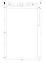
Page 22: ...22 22 Operating instructions KEA 202 INS File BA_KEA 202 INS_EN_Ver 2016 07 01 docx 22 22 16 Drilling template scale 1 1 print out without scaling...

Reviews: