background image

   Operating instructions for KEA 252 PA             

8 / 25

       File: BA_KEA 252 PA_EN_Ver 2016-07-01 


______________________________________________________________________________________ 

Alfred Kuhse GmbH 

Telephone: +49 4171-798-0 

kuhse@kuhse.de 

Subject to technical changes 

An der Kleinbahn 39, D-21423 Winsen (Luhe) 

Fax: +49 4171-798-117 

www.kuhse.de 


11. 

Display and control elements 


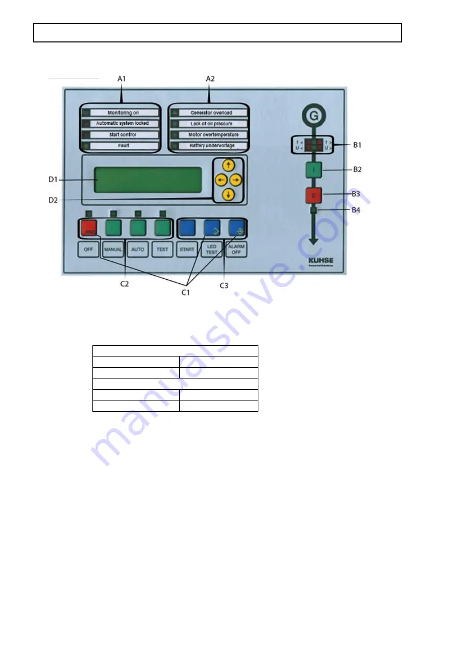
Display and control elements: 
   

          A1: 4 important operating displays  A2: 4 programmable displays


B1: Generator voltage    B2: Generator ON    B3: Generator OFF   B4: Generator ON display 

C1: Button for parameterisation    C2: Button for operating mode    C3: Other buttons 

D1: Display, illuminates, 2 lines, each with 16 characters, character height 10 mm    D2: Cursor buttons 

Parameterisation 

Off and LED Test buttons  Function:


P

ARA ON


Off and Alarm Off buttons  Function:


E

NTER


Contrast setting 

LED Test and 

 buttons 

More contrast 

LED Test and 

 buttons 

Less contrast 


11.1. 

Monitoring on 


This green display (after the genset start-up) signals the release of the operating-dependent delayed alarms. As 
soon as the motor has started up, this display flashes until the monitoring is enabled. The display goes out at 
the beginning of the shut-down process. 

11.2. 

Automatic system locked 

This red display illuminates if an alarm to be switched off has elapsed or the external quick stop was actuated. 
In order to unlock the system, the Off operating mode must be selected. If the signal cannot be cleared even in 
Off, the external quick stop is still active. 

11.3. 

Start control 

The message will be activated as soon as a start request is present in automatic mode or if manual or test mode 
has been selected. The display flashes as long as there is no start release. The display goes out as soon as the 
genset exceeds the ignition speed during start-up (recognised from the D+ signal of the generator or from the 
revolution transmitter signal). Switching on the starter is then inhibited, even if attempted manually. The starting 
generator voltage interrupts the start but does not cause the 

START CONTROL

 indicator to extinguish.  

Summary of Contents for KEA 252 PA

Page 1: ...nd displays required in VDE 0108 including the drag indicator display are fulfilled by this automatic system Also the requirements for the control of a diesel motor have been fulfilled in accordance w...

Page 2: ...to the preceding model KEA 102 PA 5 7 Automatic operation 5 7 1 Back synchronisation 5 7 2 Peak load operation 5 8 Test operation 6 9 Basic operation of automatic system 6 9 1 Operation of the display...

Page 3: ...r 13 13 2 11 Monitoring the flows 13 13 2 12 Synchronisation fault 14 13 2 13 Power controller defective 14 13 2 14 Cos controller defective 14 13 2 15 Reverse power 14 13 2 16 Maintenance interval re...

Page 4: ...the unit The connection regulations must be observed 2 The PE N must be connected to the terminal 5 of X403 3 The shields of the analogue signals must only be connected to the earthing screw next to...

Page 5: ...os or other controllers 21 Parameterisation via LWL or USB interface automatic switching or direct via the keys and the display 22 Two CAN bus interfaces 23 Diverse expansion options Modem pressure co...

Page 6: ...hrough forwards and backwards using the and cursor keys Within a group they are read like lines of a text from top to bottom The lines are selected by pressing the cursor buttons down and up If the en...

Page 7: ...isation is described in the service manual The parameters of this group can be changed without a valid ID number Switch on time of the display lighting After pressing any button the background lightin...

Page 8: ...reen display after the genset start up signals the release of the operating dependent delayed alarms As soon as the motor has started up this display flashes until the monitoring is enabled The displa...

Page 9: ...for monitoring All functions U U f f and the response values of the voltage monitors can be parametrised The un dervoltage display also appears if the measuring voltage is connected with a left rotat...

Page 10: ...tching to OFF from another operating mode a genset operation is immediately ended Previously displayed alarms except fault messages 13 and 14 are deleted as long as the respective alarm contact is sti...

Page 11: ...dynamically determined as a master and ensures the load distribution A deselected relieved genset except for the last one switches off and shuts down after the run on time 12 4 3 Peak load with mains...

Page 12: ...f a switch off alarm occurs the collective switch off alarm is output 13 Alarm messages For contact inputs the respective alarm is triggered with the closing operating current circuit or with the open...

Page 13: ...rect monitoring output a relay can be parameterised at standby current such that the message is passed on with standby current even when in OFF operating mode 13 2 7 Analogue input alarms The analogue...

Page 14: ...rised time the actual value must have been within the dead zone this alarm is issued Optionally the genset can be shut down or a peak load start command can be cancelled for example 13 2 14 Cos contro...

Page 15: ...2 Hz GEN Display of the generator voltage against the neutral conductor in the order L1 L2 and L3 and the generator frequency 6 403 400 398 V L1 2 L2 3 L3 1 G Display of the phase to phase voltages fr...

Page 16: ...indicator synchroscope Display 18 runtime until the next maintenance The operating hours counter until the next maintenance is decremented from a maximum value If the counter reading reaches 000000 an...

Page 17: ...tpoint adjuster or directly to the generator via an analogue signal After suspension of parallel operation the generator voltage is controlled in the parametrised window for the voltage control in sta...

Page 18: ...ogue input 0 20 mA channel 4 for variable power specification in mains parallel operation Battery voltage monitor Input for pick up Three free analogue inputs can be optionally equipped with sub board...

Page 19: ..._______________________________________________________________________________ Alfred Kuhse GmbH Telephone 49 4171 798 0 kuhse kuhse de Subject to technical changes An der Kleinbahn 39 D 21423 Winsen...

Page 20: ...___________________________________________________________________________ Alfred Kuhse GmbH Telephone 49 4171 798 0 kuhse kuhse de Subject to technical changes An der Kleinbahn 39 D 21423 Winsen Luh...

Page 21: ...1 docx _________________________________________________________________________________ Alfred Kuhse GmbH Telephone 49 4171 798 0 kuhse kuhse de Subject to technical changes An der Kleinbahn 39 D 214...

Page 22: ..._______________________________________________________________________________ Alfred Kuhse GmbH Telephone 49 4171 798 0 kuhse kuhse de Subject to technical changes An der Kleinbahn 39 D 21423 Winsen...

Page 23: ...1 docx _________________________________________________________________________________ Alfred Kuhse GmbH Telephone 49 4171 798 0 kuhse kuhse de Subject to technical changes An der Kleinbahn 39 D 214...

Page 24: ..._________________________________________________________________________________ Alfred Kuhse GmbH Telephone 49 4171 798 0 kuhse kuhse de Subject to technical changes An der Kleinbahn 39 D 21423 Wins...

Page 25: ..._______________________________________________________________________________ Alfred Kuhse GmbH Telephone 49 4171 798 0 kuhse kuhse de Subject to technical changes An der Kleinbahn 39 D 21423 Winsen...

Reviews: