background image

 | 13

EN

Pilot arc

The pilot arc is used to create a main cutting arc. The 

pilot arc allows arc ignition and low power without clo

-

sing the cutting circuit (connection of positive and ne

-

gative polarity). The advantage of use is when starting 

the cut on materials that do not have sufficient groun

-

ding due to surface treatment (eg paint, rust, etc.). As 

soon as the pilot arc is started and the current begins 

to flow through the ground circuit, the main cutting arc 

is automatically activated. The pilot arc is designed for 

short-term starting only, so it is equipped with a protec

-

tion that, when the arc fails, the pilot arc ends. When 

cutting of perforated materials leads to an alternating 

switching between the pilot arc and main arc cutting.

Replacing Consumables

Supplies should be replaced in the following cases:

Nozzle

The  nozzle  has  a  small  calibrated  orifice,  which  must 

be kept through. If the orifice is deformed or enlarged, 

replacement is required.

Electrode

The  electrode  has  a  small  silver  orifice  at  the  end  of 

the tip that generates plasma ions. Replacement is re

-

quired if the orifice is damaged. If excessive electrode 

consumption occurs, this may be due to poor operating 

technique, incorrect air supply, or damaged torch head.

Swirl Ring / Protective Nozzle

In case of damage, breakage, severe thermal deforma

-

tion, replacement is necessary. 

Note: Nozzles and electrodes should always be repla

-

ced at the same time to avoid uneven wear.

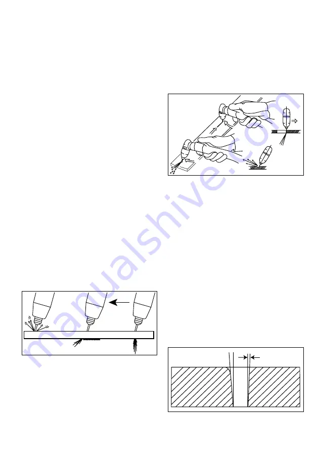
Plasma Cutting guide

Cutting speed 

(Pic. 1)

Too fast                      Too slow                    Correctly

Pic. 1

Punching material 

(Pic. 2)

When starting to punch material, tilt the torch to pre

-

vent damage to the torch accessories by the flying ma

-

terial. After punching the material, put the torch upright 

and continue cutting. Maintain a constant cutting speed 

during cutting. At the correct cutting speed, the passing 

arc on the other side of the workpiece should form an 

angle of 10° - 20°.

When punching material up to 3.2 mm, it is not nece

-

ssary to maintain the distance between the workpiece 

and the nozzle. For thicker materials up to a thickness of 


5 mm, a distance of at least 0.5 mm must be maintained. 

When punching thicker materials, it is advisable to crea

-

te  a  pilot  hole  through  the  pilot  arc,  which  increases 

the life of the consumable accessories. At the start of 

the perforation, the torch should be tilted at an angle of 

30° and straightened after being penetrated. The reco

-

mmended distance is 1.6 mm.

Pic. 2


Cutting of perforated materials

Keep the control button pressed while cutting to pre

-

vent interruption of the process. 

Cutting from workpiece edge

When starting the cut, keep the torch upright so that the 

distance is maintained. Press the torch switch to light 

the arc and start moving in the desired direction. Avoid 

cutting speeds that are too high to prevent sparks from 

flying off the top of the workpiece.

Cutting direction 

(Pic. 3)

The plasma arc has a swirling process when leaving the 

torch. For this reason, one part of the cut side is alwa

-

ys divided at a larger angle. In order to achieve greater 

perpendicularity of the cut, it is also necessary to select 

the  correct  cutting  direction.  If  you  want  to  maintain 

a smaller deviation of the circular cut along the inside 

diameter, the cutting direction must move countercloc

-

kwise. To maintain a smaller deviation along the outside 

diameter, the cutting direction must be clockwise. 

Cutting deviation

Pic. 3

Summary of Contents for MAKin CUT 40 HF

Page 1: ... 1 MAKin CUT 40 HF Návod k obsluze řezací stroj User manual CUTTING MACHINE CZ EN ...

Page 2: ...ován s využitím vy sokofrekvenčního transformátoru s feritovým jádrem transistory digitálním řízením a SMD technologií Vyniká vysokou účinností a splňuje přísné normy EU týkající se ekodesignu strojů Rychlý řídící systém zajišťuje perfekt ní stabilitu oblouku Mezi další přednosti patří energetic ky úsporný provoz a jednoduchá obsluha Stroj je určen do středního průmyslu výroby údržby či montáže Ob...

Page 3: ...o kabelu 10 25 6 Regulační n kodér 7 Regulátor vzduchu 8 Držák regulátoru 9 Vypouštěcí trubice 10 Hlavní vypínač 11 Přívodní kabel 12 Ventilátor Bezdotykové zapalování ANO Pilotní oblouk ANO Test vzduchu ANO Režim standardního řezání ANO Režim řezání děrovaných materiálů ANO Automatická kontrola hořáku ANO Automatická kontrola tlaku vzduchu ANO Tepelná ochrana ANO Přehled funkcí a jejich parametry...

Page 4: ...ce 2 Kontrolka zapnutí Pozice 3 Kontrolka poruchy Pozice 4 Kontrolka chyby hořáku Pozice 5 Kontrolka signalizace řezání Pozice 6 Test vzduchu Pozice 7 Režim standardního řezání Pozice 8 Režim řezání děrovaných materiálů Pozice 9 Tlačítko přepínání režimů CZ 1 6 7 9 2 3 4 5 8 ...

Page 5: ...duchu Postupným stlačením tlačítka přepínání režimů nastav te funkci Test vzduchu dojde k otevření ventilu a prou dění vzduchu Tato funkce se používá pro nastavení a testování správného řezacího tlaku vzduchu Signalizace poruchy K aktivaci dochází zjištěním příliš vysokého napájecího napětí nebo proudu přehřátím a poruchou stroje Po kud je signalizace aktivována řezací výkon je blokován Nastavení ...

Page 6: ...lost řezání obr 1 Příliš rychle Příliš pomalu Správně Obr 1 Proděrování materiálu obr 2 Při zahájení proděrování materiálu nakloňte hořák tak abyste zabránili poškození příslušenství hořáku odletují cím materiálem Po proděrování materiálu uveďte hořák do vzpřímené polohy a pokračujte v řezání V průběhu řezání udržujte konstantní rychlost řezání Při správné řezací rychlosti by procházející oblouk n...

Page 7: ...a I přes Vaše požadované technické dovednosti nezbytné pro opravu řezacího stroje Vám v případě poškození do poručujeme kontaktovat naše smluvní servisní partnery nebo servisní oddělení naší firmy Údržba Varování Před tím než provedete jakoukoli kontrolu nebo údržbu uvnitř stroje odpojte jej od elektrické sítě Při plánování údržby stroje musí být vzata v úvahu míra a okolnosti využití stroje Šetrn...

Page 8: ...pálit oblouk Řezací kabely nejsou připojeny Připojte oba kabely Řezací kabely jsou poškozeny Opravte vyměňte poškozený kabel Zemnící kabel není připojen Zkontrolujte připojení zemnícího kabelu 6 Oblouk lze zapálit obtížně Chybně připojeny řezací kabely Zkontrolujte připojení Pracovní svorky jsou pokryty nečistotami Zkontrolujte a očistěte pracovní svorky 7 Nestabilní řezací oblouk Výkon oblouku je...

Page 9: ...ore transis tors digital control and SMD technology It excels in high efficiency and meets stringent EU standards on machine ecodesign The fast control system ensures perfect arc stability Other advantages include energy efficient ope ration and simple operation The machine is designed for medium industry production maintenance or as sembly Package contents operating instructions and safety instru...

Page 10: ...0 25 6 Regulatory n coder 7 Air regulator 8 Controller bracket 9 Drain tube 10 Main switch 11 Power cable 12 Fan Contactless ignition YES Pilot arc YES Air test YES Standard cutting mode YES Perforated material cutting mode YES Automatic Torch check YES Automatic air pressure control YES Thermal protection YES Overview of functions and their parameters 2 7 8 9 6 1 5 11 12 4 10 3 ...

Page 11: ...etting Position 2 Power on LED Position 3 Fault indicator Position 4 Torch error indicator Position 5 Cutting indicator light Position 6 Air test Position 7 Standard cutting mode Position 8 Perforated material cutting mode Position 9 Mode switch button 1 6 7 9 2 3 4 5 8 ...

Page 12: ... open the valve and air flow This function is used to set and test the correct air cutting pressure Fault signaling Activation occurs when the supply voltage is too high voltage or current overheating and machine malfunc tions If signaling is activated cutting power is blocked Air pressure adjustment Correct air pressure adjustment has a major effect on the result cutting If the pressure is set in...

Page 13: ... to pre vent damage to the torch accessories by the flying ma terial After punching the material put the torch upright and continue cutting Maintain a constant cutting speed during cutting At the correct cutting speed the passing arc on the other side of the workpiece should form an angle of 10 20 When punching material up to 3 2 mm it is not nece ssary to maintain the distance between the workpie...

Page 14: ...machine main switch Maintenance Warning Disconnect it from the power supply befo re carrying out any inspection or maintenance inside the machine When planning machine maintenance account must be taken of the rate and circumstances of machine use Gentle use and preventive maintenan ce help prevent unnecessary malfunctions and defects Inspection and maintenance intervals should be selec ted more fr...

Page 15: ...n of the machine 5 The arc cannot be ignited The welding cables are not connected Connect both welding cables The welding cables are damaged Repair replace damaged cable The ground cable is not connected Check the grounding cable connection 6 The arc is difficult to ignite Incorrectly connected cutting cables Check the connection The work clamps are covered with dirt Check and clean the work clamp...

Page 16: ...lozásuvka 10 25 Quickcoupling 10 25 4 N kodér N coder 5 PCB ovládací PCB control 6 Kryt Cover 7 Madlo Handle 8 Regulátor vzduchu Air regulator 9 Vypínač hlavní Main switch 10 Ventilátor Fan 11 Ventil plynový Air valve 12 PCB výkonová PCB power Seznam náhradních dílů List of spare parts 1 2 3 4 5 6 7 8 9 10 11 12 ...

Page 17: ...dress of manufacturer 6 Výrobní číslo Serial number 7 Normy Standards 8 Proud při zatížení Current under load 9 Napětí při zatížení Voltage under load Výrobní štítek Production plate 2 3 4 1 5 7 8 6 9 Schéma zapojení centrální zásuvky Central socket wiring diagram 1 2 3 4 5 6 7 8 9 Zkratové spojení Pilot Arc Ovládací tlačítko Control bu on Short circuit connec on Pilotní oblouk ...

Page 18: ...18 Elektrotechnické schéma Electrical scheme ...

Page 19: ...výrobku Type MAKin CUT 40 HF Výrobní číslo stroje Serial number Výrobce Producer Razítko OTK Stamp of Technical Control Department Datum Date of production Kontroloval Inspected by Záznam o provedeném servisním zákroku Repair note Datum převzetí servisem Date of take over Datum provedení opravy Date of repair Číslo reklam protokolu Number of repair form Podpis pracovníka Signature of serviceman ...

Page 20: ...20 Výrobce si vyhrazuje právo na změnu The producer reserves the right to modification 06 2020 ...

Reviews: