10 / 81
Issued: 22.04.2016 Version: Spez KR 20-3 V2
Electrical installations
In-line wrist
The robot can be equipped with a triple-axis in-line wrist for a payload of 20 kg.
The in-line wrist is screwed to the arm via the flange. End effectors are at-
tached to the mounting flange of axis 6. Each axis has a measuring device,
through which the mechanical zero of the respective axis can be checked by
means of an electronic probe (accessory) and transferred to the controller. Di-
rections of rotation, axis data and permissible loads can be found in Chapter
(
>>>
The in-line wrist is driven by the motors on the rear of the arm by means of
toothed belts (A4 and A5) and shafts. The drive power within the in-line wrist
is transmitted by means of bevel and spur gear units.
The mounting flange conforms, with minimal deviations, to ISO 9409-1:2004.
Arm
The arm of this robot variant is designed as a cast hollow structural element
with interfaces to the in-line wrist and link arm. The interfaces are screwed
connections. The coaxial, one-piece drive shafts for axes 4 to 6 are mounted
in the arm housing. Wrist axes A4 and A5 are driven by the wrist axis motors
(drive units) via toothed belts, while axis A6 is driven directly via a push-fit con-
nection.
The three drive units for the wrist axes are located at the rear of the arm hous-
ing and are arranged one above the other.
Link arm
The link arm is the assembly located between the arm and the rotating column.
It consists of the link arm body with the buffers for axis 2.
Rotating column
The rotating column houses the motors of axes 1 and 2. The rotational motion
of axis 1 is performed by the rotating column. This is screwed to the base
frame via the gear unit of axis 1 and is driven by a motor in the rotating column.
The link arm is also mounted in the rotating column.
Base frame
The base frame is the base of the robot. It is screwed to the mounting base.
The flexible tube for the electrical installations is installed in the base frame.
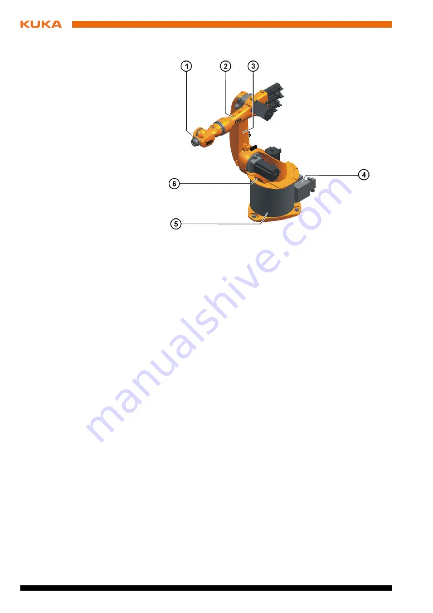
Fig. 3-2: Main assemblies of the manipulator
1
In-line wrist
4
Electrical installations
2
Arm
5
Base frame
3
Link arm
6
Rotating column
Summary of Contents for KR 20-3
Page 6: ...6 81 Issued 22 04 2016 Version Spez KR 20 3 V2 KR 20 3...
Page 8: ...8 81 Issued 22 04 2016 Version Spez KR 20 3 V2 KR 20 3...
Page 12: ...12 81 Issued 22 04 2016 Version Spez KR 20 3 V2 KR 20 3...
Page 42: ...42 81 Issued 22 04 2016 Version Spez KR 20 3 V2 KR 20 3...
Page 62: ...62 81 Issued 22 04 2016 Version Spez KR 20 3 V2 KR 20 3...
Page 68: ...68 81 Issued 22 04 2016 Version Spez KR 20 3 V2 KR 20 3...
Page 70: ...70 81 Issued 22 04 2016 Version Spez KR 20 3 V2 KR 20 3...
Page 78: ...78 81 Issued 22 04 2016 Version Spez KR 20 3 V2 KR 20 3...
Page 81: ...81 81 Issued 22 04 2016 Version Spez KR 20 3 V2 KR 20 3...


