2
Basic modules and servo power modules (continued)
19 of 70
Hardware R2.2.8 11.98.02 en
2.8
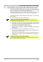
Current regulator programming ($G_COE_CUR) of the Powermodule
The powermodules PM0 and PM6 contain a programmable potentiometer (EEPot), with
which the current regulator can be optimized for the appropriate robot type. The optimum
value for this setting is entered in the machine data ($G_COE_CUR).
When exchanging a PM0--600 , PM6--600 or a KRC1--control cabinet with powermodule, the
correct current settings should be taken over and saved on the new powermodule.
The following proceedings should be followed.after a power module or control cabinet has
been exchanged:
(1) Switch on the KRC1--control cabinet and let it start up.
[
Only for power modules with write--protect jumpers:
(visible from front under cutout in plate, lettering:“Betrieb/Programmierung”) Put the
jumper in the position “Programmierung”].
(2) With the KCP on the BOF (GUI), call up the menu option HELP--> VERSION.Check
if the displayed robot type correspnds with the actual installed machine. When this is
not the case, the correct machine data has to be loaded.
(3) Call up the menu option MONITOR--> VARIABLE --> MODIFY.
A window for the entry of variables is displayed in the field “NAME” enter the following:
$PROG_EEPOT
(4) Press the softkey “NEW VALUE” and enter the value 1 (for axis no.1).
When the enter key is pressed, the current regulator of axis 1 is programmed with the
value that is saved in the machine data.
By entering “2” in the field “NEW VALUE”, the axis 2 can be programmed and so on.
All the axes that are controlled by the robot including external axes, must be program-
med in this way.
Only for power modules with write--protect jumpers
:
when the current regulators of all axes have been programmed, the write--protect jum-
per must be replaced in the position “Betrieb”.
Summary of Contents for KR C1
Page 1: ...Hardware R2 2 8 11 98 02 en 1 of 70 SOFTWARE KR C1 Hardware Release 2 2...
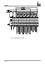
Page 30: ...Hardware 30 of 70 Hardware R2 2 8 11 98 02 en Fig 13 Circuit diagram X931 X604...
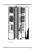
Page 32: ...Hardware 32 of 70 Hardware R2 2 8 11 98 02 en Fig 15 Inputs...
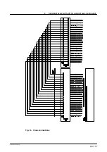
Page 34: ...Hardware 34 of 70 Hardware R2 2 8 11 98 02 en...
Page 35: ...35 of 70 Hardware R2 2 8 11 98 02 en...


