5
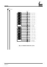
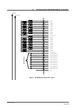
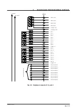
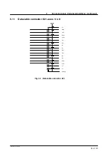
Connector panel / Peripheral interfaces (continued)
37 of 70
Hardware R2.2.8 11.98.02 en
5.1
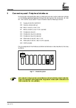
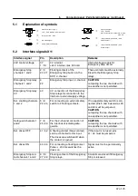
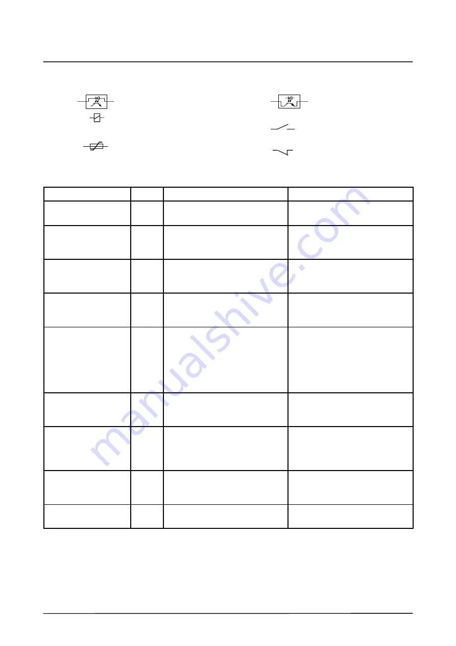
Explanation of symbols
load current for 2 A output
electronic output
15V - - 30V DC
electronic input, logic ”1”
15 V - - 30 V (approx. 6.5 mA at 24 V)
relay coil 18 V - - 30 V
relay contact max. 500 mA / 30 V
=
=
=
=
=
*
low active signal
=
power protection 500 mA
relay contact max. 500 mA / 30 V
=
make contact
break contact
max.: 2 A
min.: 0.02 A
5.2
Interface signals X11
Interface signal
Pin
Description
Remarks
24V control voltage
37
1 / 19
0 V internal
+24 V internal, max. 500 mA
Internal voltage supply for
Emergency Stop circuit
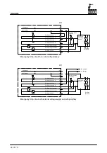
Emergency Stop
channels 1 and 2
2 / 3
20 / 21
Floating contacts of the
Emergency Stop button on the
KCP, 2--channel.
These contacts must be externally
linked to the Emergency Stop
relays.
Emergency Stop relay
channels 1 and 2
4
22
Emergency Stop input, 2--channel
CAUTION
Jumpering the two channels with
one another is not permitted.
Emergency Stop relay
0V
40
0 V connection of the Emergency
Stop relays for connection to the
internal or external supply voltage.
Ext. enabling channels
1 and 2
5 / 6
23 / 24
For connecting an external safety
switch to 2 floating contacts.
If no supplementary switch is con-
nected, pins 5 and 6 as well as 23
and 24 must be jumpered.
CAUTION
Jumpering the two channels with
one another is not permitted.
Safeguard channels 1
and 2
7 / 8
25 / 26
For the 2--channel connection of
the interlock of isolating safe-
guards.
CAUTION
Jumpering the two channels with
one another is not permitted.
Ext. drives OFF
41 / 42 A floating contact (break contact)
can be connected to this input.
The drives are switched off when
the contact is opened.
If this input is not used, pins
41 / 42 must be jumpered.
Ext. drives ON
43 / 44 For connecting a floating contact.
Pulse
≥
200 ms switches the
drives on.
Signal must not be permanently
active.
Emergency Stop con-
tact channels 1 and 2
9 / 10
27 / 28
Floating contact of the Emergency
Stop relays.
Contacts are closed if Emergency
Stop is released.
Summary of Contents for KR C1
Page 1: ...Hardware R2 2 8 11 98 02 en 1 of 70 SOFTWARE KR C1 Hardware Release 2 2...
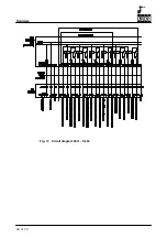
Page 30: ...Hardware 30 of 70 Hardware R2 2 8 11 98 02 en Fig 13 Circuit diagram X931 X604...
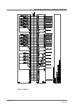
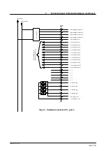
Page 32: ...Hardware 32 of 70 Hardware R2 2 8 11 98 02 en Fig 15 Inputs...
Page 34: ...Hardware 34 of 70 Hardware R2 2 8 11 98 02 en...
Page 35: ...35 of 70 Hardware R2 2 8 11 98 02 en...

