7
Resolver--to--Digital Converter (RDC) (continued)
63 of 70
Hardware R2.2.8 11.98.02 en
7.3
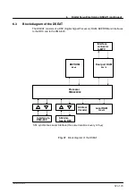
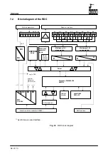
Operating principle of the RDC
Power supply unit:
The 27V supply voltage generated in the PM is fed via the encoder cable to the power supply
unit, which adapts it to provide all the voltages required by the RDC:
+5 V
Processor, logic components, temperature sensors
+12 V
Output stage of the sine--wave generator
#
12 V
Amplifier, multiplexer, A/D converter
Processor:
The central component of the RDC is a floating--point processor (TMS320C32) with 60 MHz
clock frequency.
The processor acts purely as a RAM machine. The program code is not stored on the RDC
but is loaded via the serial interface. The necessary boot code and basic software are stored
in an 8Kx8 EEPROM.
The RAM size is 32 KByte. Maximum speed is guaranteed by the 32--bit data bus width,
15 ns access time and therefore 0 wait states.
Sine--wave generator:
The input voltage is a square--wave voltage from the processor. The frequency of 8 kHz is
therefore determined by the software.
The amplitude can be set by software in the range from 4.5 Vpp to 7 Vpp by means of an
EE--potentiometer.
The square--wave voltage is converted to sine--wave voltage by filters.
The maximum output current is 200 mA rms (corresponding to the maximum load with 8 re-
solvers). The output is thermally protected against short--circuits.
Resolver evaluation:
The resolver response signals (8 x SIN and 8 x COS) are fed to 2 multiplexers and then con-
verted from analog to digital signals. A/D conversion takes place at every peak value of the
carrier frequency (8 kHz).
Synchronization is easily implemented, because the carrier frequency is generated by the
processor.
The position of the resolver can now be calculated from the two values for SIN and COS.
Motor temperature:
Each motor contains a temperature sensor (analog sensor KTY 84) with an essentially linear
characteristic. This sensor is supplied with constant current. The voltage is filtered, fed to
one of the two multiplexers and then converted from analog to digital, thereby providing the
processor with the temperature of each motor in the form of a 12--bit value.
Actual value storage:
All actual values (including motor temperature) are transmitted to the DSEAT at the commu-
tation frequency (every 125
μ
s).
When the controller is switched OFF, the actual values are stored in the EEPROM. For this
purpose, the controller voltage must be briefly maintained by (rechargeable) back--up bat-
tery. When the software has completed all its tasks, a ”back--up stop” bit is transmitted to the
PM6, which then switches off the battery (in the absence of this bit, the battery is switched
off by the hardware after 70 seconds).
When the controller is switched ON, it checks whether the manipulator has been moved: the
present actual value from the resolver (delivered by the RDC) is compared with the last value
stored in the RDC EEPROM before the controller was switched off.
Summary of Contents for KR C1
Page 1: ...Hardware R2 2 8 11 98 02 en 1 of 70 SOFTWARE KR C1 Hardware Release 2 2...
Page 30: ...Hardware 30 of 70 Hardware R2 2 8 11 98 02 en Fig 13 Circuit diagram X931 X604...
Page 32: ...Hardware 32 of 70 Hardware R2 2 8 11 98 02 en Fig 15 Inputs...
Page 34: ...Hardware 34 of 70 Hardware R2 2 8 11 98 02 en...
Page 35: ...35 of 70 Hardware R2 2 8 11 98 02 en...

