Hardware
66 of 70
Hardware R2.2.8 11.98.02 en
7.5.1
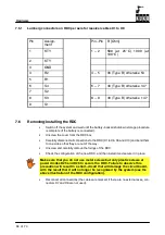
Lumberg connectors on RDC per axis for resolver cables X1 to X8
Pin
Assign-
ment
Pin--Pin
R [Ohm]
1
KTY
1 -- 2
588 (at 25
_
C) 1000 (at
100
_
C)
2
KTY
3
GND
4
R2
4 -- 5
36 (Type B) otherwise 53
5
R1
6
S4
6 -- 7
48 (Type B) otherwise 147
7
S2
8
S3
8 -- 9
48 (Type B) otherwise 147
9
S1
7.6
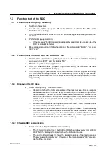
Removing/Installing the RDC
G
Switch off the system and wait until the battery--backed shutdown storage procedure
is complete (if the battery is connected).
G
Unscrew the cover from the RDC box.
G
Carefully disconnect all connections to the RDC (X1 to X6, X9 and X10) and bend them
to one side so that they are out of the way.
G
Unscrew and carefully remove the fixings of the RDC.
G
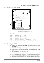
Check the configuration of the new RDC, and then install it and secure it in place.
Make sure that you do not use metal screws but only plastic screws at
power diodes D25 and D26 to secure the RDC. Failure to observe this
precaution will result in a short--circuit that will damage the circuit board,
with the result that it will no longer be recognized by the system (see the
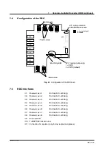
above illustration of the RDC configuration).
G
Reconnect all connections (the cables are marked; if there are no external axes, con-
nectors X7 and X8 are not used).
Summary of Contents for KR C1
Page 1: ...Hardware R2 2 8 11 98 02 en 1 of 70 SOFTWARE KR C1 Hardware Release 2 2...
Page 30: ...Hardware 30 of 70 Hardware R2 2 8 11 98 02 en Fig 13 Circuit diagram X931 X604...
Page 32: ...Hardware 32 of 70 Hardware R2 2 8 11 98 02 en Fig 15 Inputs...
Page 34: ...Hardware 34 of 70 Hardware R2 2 8 11 98 02 en...
Page 35: ...35 of 70 Hardware R2 2 8 11 98 02 en...


