background image

DE


Betriebsanleitung

GB


Operating instructions

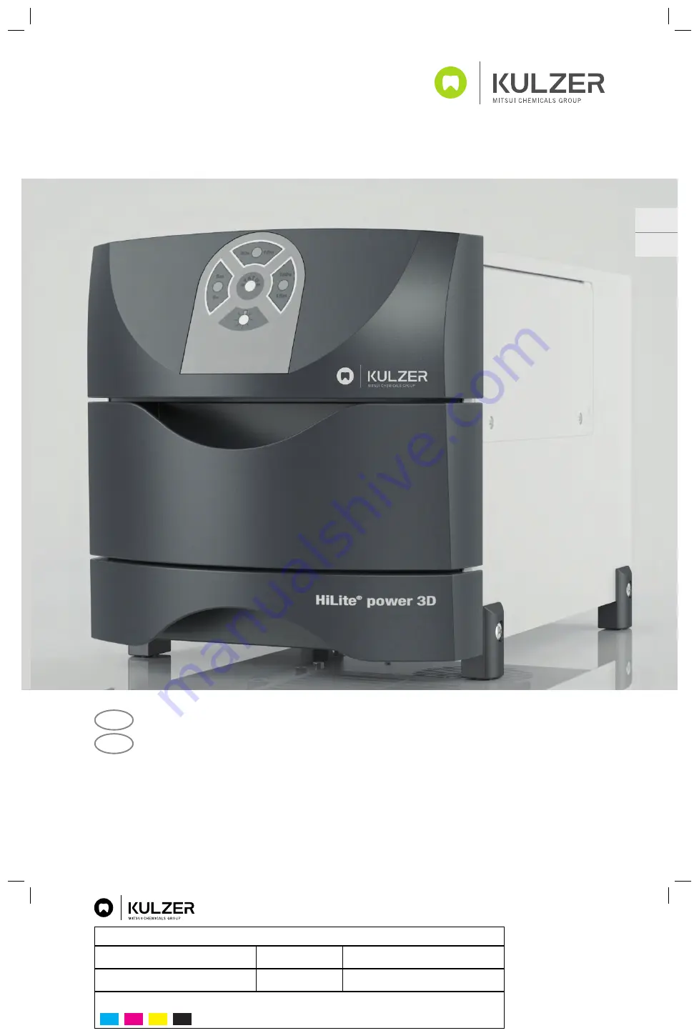
HiLite

®

 power 3D

Dateiname:

  00US_66069514_12_W22002_BA_HiLite power_3D_DE-GB

SAP-Nr: Version
66069514 12

KG-Toolbox-Nr:

W22002

Format: Falzmaß:

420 x  280 mm 

210 x 280 mm

Projektmanager:
Markus Weik

AK-Version:

03

Datum 

KG Freigabe am 

07.05.2019 08.05.2019

W22002_66069514_12 US-VS_210x280 
BA_HiLite power_3D_DE-GB 

Layout Page: TITEL 

EURO / Pantone   

Sonderfarben


Druckverfahren: 

Digitaldruck


varnish DieCut var.Data

DE

GB

Vorgänger: 
W18520

Summary of Contents for HiLite power 3D

Page 1: ...069514 12 KG Toolbox Nr W22002 Format Falzma 420 x 280 mm 210 x 280 mm Projektmanager Markus Weik AK Version 03 Datum KG Freigabe am 07 05 2019 08 05 2019 W22002_66069514_12 US VS_210x280 BA_HiLite po...

Page 2: ......

Page 3: ...itenansicht bei ge ffneter Wartungsklappe 5 5 3 R ckansicht 6 6 Ger tebeschreibung 6 7 Inbetriebnahme 6 7 1 Transport 6 7 2 Aufstellung 7 7 3 Funktionspr fung 7 7 4 Netzanschluss 7 7 5 Installation Fi...

Page 4: ...linien Niederspannungs Richtlinie 2014 35 EU EMV Richtlinie 2014 30 EU Angewandte harmonisierte Normen EN 61010 1 2011 07 EN 61010 2 010 2015 05 EN 61326 1 2013 07 Bei einer nicht mit uns abgestimmten...

Page 5: ...ne Originalersatzteile und Zubeh r verwendet werden Die Verwendung anderer Teile birgt unbekannte Risiken und ist in jedem Fall zu unterlassen Die Funktionst chtigkeit und Sicherheit des Ger tes ist n...

Page 6: ...nzelnen Polymerisationen von 90 s Pausenzeiten von z B 30 s bis 60 s einzuhalten um dem Ger t die M glichkeit zum Abk hlen zu geben L fter l uft 4 Lieferumfang Pr fen Sie bei Lieferung des Ger tes ob...

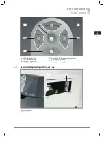
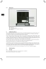
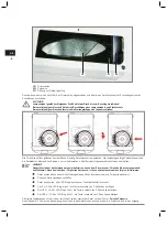
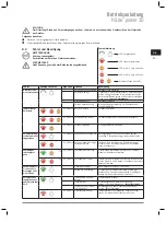
Page 7: ...s Zwischenpolymerisation und 10 Minuten 3D Druck 12 Taster 180 s Endpolymerisation und 15 Minuten 3D Druck 9 LED Lampenkontrolle 10 Taster 6 s Angelieren und 5 Minuten 3D Druck 5 2 Seitenansicht bei...

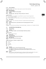
Page 8: ...rsten 15 Sekunden abgebrochen werden W hrend diesen ersten 15 Sekunden blinkt die Status LED Nach Ablauf der Zeit ert nt ein akustisches Signal und die Schublade wird wieder entriegelt Der w hrend des...

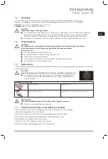
Page 9: ...fte Teile ausgetauscht werden keine Sch den am Stecker und der Isolierung des Netzkabels vorhanden sind der Netzstecker zur Steckdose passen muss 7 4 Netzanschluss Auf der R ckseite des Ger tes befind...

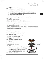
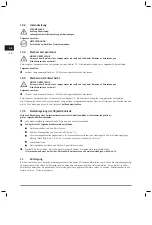
Page 10: ...alten HINWEIS Neuger te sind bei Auslieferung bereits initialisiert und nach dem Einsetzen der Chipkarte des Lampenmoduls betriebsbereit Nach dem Lampen Chipkarten Austausch ist das neue Lampenmodul w...

Page 11: ...vorgangs ffnen Polymerisationsvorgang muss sofort automatisch unterbrochen werden Sollte die laufende Polymerisation nicht unterbrochen werden ist umgehend der Service zu kontaktierten siehe Kapitel...

Page 12: ...15 Sekunden blinkt die Status LED Um eine optimale Polymerisation zu erreichen muss die prothetische Arbeit durch den integrierten L fter gleichm ig und gut gek hlt werden Dies ist nur bei einer zentr...

Page 13: ...0 ms Endschalter hat ausgel st Wartungsklappe und oder Schublade korrekt schlie en Polymerisation ggf erneut durchf hren 3 x 500 ms Kein Lampenmodul einge setzt oder defekt Lampenmodul einsetzen und P...

Page 14: ...tel und Desinfektionsmittel auf alkoholischer Basis verwenden Keine Laugen tzende oder scheuernde Stoffe Methanol Amine technische L semittel organische Verbindungen Methylmethacrylat und Methacryls u...

Page 15: ...hmutzung mit Druckluft gereinigt werden Diese Arbeiten nicht im Geb ude durchf hren 10 Instandhaltung Instandsetzung 10 1 Instandhaltung ACHTUNG Nur mit Original Ersatzteilen ist die Funktionsf higkei...

Page 16: ...icht relevant Auf Sauberkeit achten 10 5 Notentriegelung der Objektschublade Wird nach Beendigung eines Polymerisationsprozesses die Objektschulblade nicht automatisch ge ffnet gibt es folgende Abhilf...

Page 17: ...0 800 437 25 22 bzw wenden Sie sich an Ihren H ndler oder die Kulzer Niederlassungen in Ihrem Land WICHTIG Gekennzeichnete Ger te d rfen nicht ber die kommunalen Entsorgungsstellen entsorgt werden 13...

Page 18: ...16 DE 14 Schaltplan 14 1 Klemmenbelegungsplan...

Page 19: ...n zur Verf gung Ansprechpartner in den L ndern und weitere Informationen finden Sie direkt mit dem nebenstehenden QR Code oder auf unserer Homepage www kulzer com 16 Dokumentenhistorie 2017 03 Erstaus...

Page 20: ......

Page 21: ...nance flap being opened 5 5 3 Rear view 6 6 Device description 6 7 Putting the unit into operation 6 7 1 Transport 6 7 2 Installation 7 7 3 Function check 7 7 4 Mains connection 7 7 5 Installation fil...

Page 22: ...directive 2014 35 EU EMC directive 2014 30 EU Applied harmonzied standards EN 61010 1 2011 07 EN 61010 2 010 2015 05 EN 61326 1 2013 07 The declaration shall become invalid if any modification we have...

Page 23: ...electrical equipment of the unit may only be performed by adequately trained service companies and in the safe condition voltage cleared Only permissible original spare parts must be used The use of...

Page 24: ...polymerisation operation of 90 seconds or 180 seconds for example so that the device may cool down ventilator running 4 Scope of delivery Check that all components are in perfect condition on delivery...

Page 25: ...polymerisation and 10 minutes 3D printing 12 180 second button end polymerisation and 15 minutes 3D printing 9 LED lamp control 10 6 second button hardening and 5 minutes 3D printing 5 2 Lateral view...

Page 26: ...nking during first 15 seconds At the end an acoustic signal is heard and the drawer is unlocked again The fan which is activated automatically during operation continues to run so that the interior of...

Page 27: ...ctive parts are replaced the plug and the insulation of the power cord are not damaged the mains plug and the socket must be compatible 7 4 Mains connection At the rear of the unit there is a cold app...

Page 28: ...nformation in the event of complaints or service NOTE New units are pre initialized when shipped and are ready for use after insertion of chip card and bulb After bulb and chip card replacement you ne...

Page 29: ...n the light reflector Check the correct function of limit switch Start 6 second cycle and open drawer during process abnormal use Flashing must stop immediately If not please contact your local servic...

Page 30: ...econds The built in ventilator must cool the composite material evenly and well to ensure an excellent polymerisation result This will only happen if the product is positioned in the centre The 6 seco...

Page 31: ...rted or aborted 3 x 500 ms Limit switch was activated Close maintenance flap and or drawer correctly If necessary repeat polymerisation process 3 x 500 ms No flash lamp inserted or flash lamp defect I...

Page 32: ...ress cracks in the housing Observe the following information Use mild alcohol based cleaning and disinfection agents Do not use any alkali solutions corrosive or chafing materials methanol amine techn...

Page 33: ...n the filter if it becomes dirty because of compressed air Do not perform this work in the building 10 Maintenance Repair 10 1 Maintenance CAUTION The device will only function properly if original sp...

Page 34: ...emoving the flash lamp The upper and underside of the filter disc are identical so that incorrect mounting is avoided Cleanliness must be ensured 10 5 Emergency unlock of drawer If automatic unlocking...

Page 35: ...r country CAUTION Marked equipment must not be brought to local waste disposal centres 13 Technical Data 13 1 Mains connection Value Unit Nominal voltage 100 V 115 V 230 V Nominal frequency 50 60 Hz F...

Page 36: ...16 GB 14 Circuit diagram 14 1 Terminal allocation scheme...

Page 37: ...ountries and more information are available by the displayed QR code or at our website www kulzer com 16 Document history 2017 03 First edition HiLite power 3D 2017 07 Document Version 11 Changed name...

Page 38: ......

Page 39: ......

Page 40: ...W22002 DE GB 66069514 12 2019 04 Manufacturer Kulzer GmbH Leipziger Stra e 2 63450 Hanau Germany W22002_66069514_12 US RS_210x280 BA_HiLite power_3D_DE GB...

Reviews: