background image

- 10 -

GB

DE

GB

FR

ES

IT

PT

NL

SE

DK

NO

FI

GR

7.6.3  Filter drawer


Has the filter been inserted?


Clean or replace very dirty filters.

7.6.4  Inside the machine


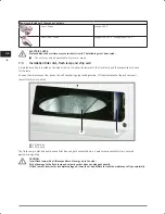
Has the flash lamp been inserted as far as it will go?


Has the chip card been correctly inserted into the card reader?


Is the filter disc in position and clean?

8 Appliance

8.1 

Working with the machine   


Connect the machine to the power supply and switch it on.

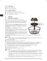
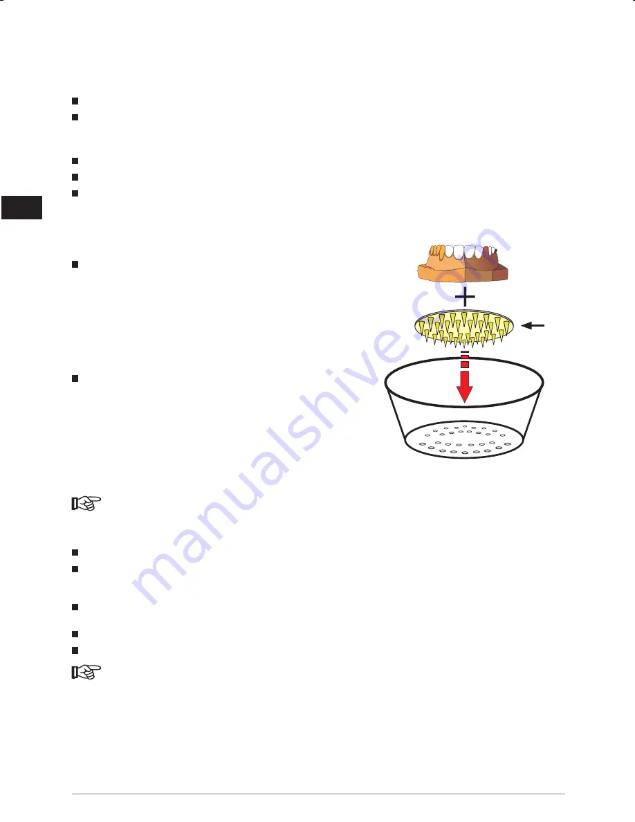
Make sure that the material is placed in the machine on the supplied object 
holder (if possible!) and not with the whole plaster model. The large light 
reflector allows this to be done, but it significantly prevents the cooling 
capability. 

Warming can be reduced with the “

Model tray

” spacer when the 180 second 

light polymerisation is used frequently. For this purpose, the model must 
be placed on the tray with the feet pointing downwards in order to achieve 
better ventilation.


Delivery form: 

2 pieces “

Model tray”

 REF 66017525

Open the polymerisation drawer and insert the prosthetic material in the light 
reflector. Close the drawer. Press the button for the respective polymerisation 
cycle. The respective LED ring is lit.  
The drawer is locked (not in the 6 second cycle). At the end of the polyme-
risation time an acoustic signal (buzzer) is heard and the drawer is unlocked 
again. Remove the prosthetic restoration and exchange the reflector pot if it 
is heavily contaminated or clean it.  
The fan which started at the beginning of polymerisation continues to run until the interior of the unit has been cooled down  
to a large extent.

 NOTE

  The built-in ventilator must cool the prosthetic material evenly and well to ensure an excellent polymerisation result. 

This will only happen if the product is positioned in the centre.

Observe the following information:


Place the prosthetic material in the centre of the light reflector.


Align the polymerisation product with the light source to ensure an excellent polymerisation result. If polymerisation is 
advantageous on the model, place the model with the greatest possible angle to the light reflector wall. This keeps the 
ventilation holes in the floor free. An angular position is favourable as lateral exposure is better on the facing.


When positioning the product, ensure that it is aligned beneath the edge of the light reflector. Otherwise,  
the drawer will not close and the object will touch the window pane in the machine.


Insert the drawer as far as it will go.


Select the required polymerisation time and press the button.

 NOTE

  The 6 second polymerisation time is used to harden the material. All components of Signum

®

 (exception: Opaque)  

can be pre-polymerised using the 6 second polymerisation time if a maximum layer thickness of 2 mm is not exceeded. 
Then carry out intermediate polymerisation for 90 seconds and end polymerisation for 180 seconds.


To ensure extended service life of the unit, the interior of the unit should have been cooled down sufficiently before the 
unit is switched off. The unit should not be switched off as long as the fan is not in standby-mode. (Fan is not turned 
off completely).


Attempting to pull out the drawer may result in blocking of the locking magnet. In such cases the drawer needs to be 
re-inserted and the unit must be switched off and on; then the drawer can be opened again.

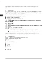
Model tray

Summary of Contents for HiLite power

Page 1: ...DE Betriebsanleitung GB Operating instructions HiLite power DE GB...

Page 2: ......

Page 3: ...llation Filterscheibe Lampenmodul und Chipkarte 8 7 6 Ger tepr fung 9 7 6 1 Bedienfeld 9 7 6 2 Schublade f r Polymerisationsgut 9 7 6 3 Filterschublade 10 7 6 4 Innenraum des Ger tes 10 8 Bedienung 10...

Page 4: ...nentyp G ltig ab Serien Nr Lichtpolymerisationsger t HiLite power 2017 07 0001 ff 1 3 EG Konformit tserkl rung Hiermit erkl ren wir Kulzer GmbH Leipziger Stra e 2 63450 Hanau Germany dass die nach fol...

Page 5: ...ren eines Ger tebuches In diesem Ger tebuch sind Pr fungen sowie alle wesentlichen Arbeiten z B Instandsetzungen nderungen zu dokumentieren Bewahren Sie diese Bedienungsanleitung an einem sicheren Ort...

Page 6: ...n aufgrund seiner Qualifikation sachgerecht ausf hren kann m gliche Gefahren bei der Arbeit mit dem Ger t erkennen kann ACHTUNG Beim Auftreten besonderer Probleme die in dieser Betriebsanleitung nicht...

Page 7: ...5 Filter 6 Schublade f r Filter 7 Wartungsklappe 2 Reflektortopf 3 Objekthalter 4 Schublade f r Polymerisationsgut 8 LED Statuskontrolle 11 Taster 90 s Zyklus Zwischenpolymerisation 12 Taster 180 s Z...

Page 8: ...enansicht bei ge ffneter Wartungsklappe 13 Lampenmodul 14 Chipkarte 5 3 R ckansicht 15 Netzschalter 16 Spannungswahlschalter 17 Kaltger testecker mit integrierten Sicherungen 18 Typenschild 1 4 6 13 1...

Page 9: ...nd Gewicht siehe Kapitel 13 Technische Daten 7 2 Aufstellung Das HiLite power ist auf einer festen nicht brennbaren Fl che Labortisch Untergestelle so aufzustellen dass sich ein waagerechter sicherer...

Page 10: ...ampenzugeh rigen Chipkarte erm glicht Zum ffnen der Wartungsklappe die selbsthaltenden Verschlussschrauben l sen Wartungsklappe nach oben anheben und entnehmen Filterscheibe in die daf r vorgesehene A...

Page 11: ...folgende Hinweise bitte beachten Bei Austausch des Lampenmoduls ist die Chipkarte ebenfalls auszutauschen Im Reklamationsfall ist das Lampenmodul immer mit Chipkarte zur ck zu senden Bei Nichtbeachtun...

Page 12: ...testgehend abgek hlt ist HINWEIS Um eine optimale Polymerisation zu erreichen muss die prothetische Arbeit durch den integrierten L fter gleichm ig und gut gek hlt werden Dies ist nur bei einer zentra...

Page 13: ...schmutzung wechseln 8 2 Fehler und Beseitigung NETZTRENNUNG Achtung Lebensgefahr Vor Arbeiten am Ger t den Netzstecker ziehen STROMSCHLAG Hohe Spannungen sind beim Ber hren lebensgef hrdend Fehler Anz...

Page 14: ...oder Objekte besser positionieren Bodenfl che des Reflektortopfes ist durchgebogen und klemmt den L ftermotor Reflektortopf kontrollieren ggf Boden ausrichten oder Topf austauschen L fter defekt L fte...

Page 15: ...s durchf hren 9 2 3 Lampenreflektor Reinigung Mindestens 1 mal im Monat mit einem fusselfreien weichen Wischtuch abwischen NETZTRENNUNG Achtung Lebensgefahr Vor Arbeiten am Ger t den Netzstecker ziehe...

Page 16: ...hsel Lampenmodul HEISSE OBERFL CHE Kurz nach dem Betrieb ist das Lampenmodul sehr hei und f hrt beim Ber hren zu Verbrennungen Siehe Zeichen am Ger t Folgendes beachten Vor dem Lampenwechsel Ger t ca...

Page 17: ...Sie unser Call Center unter der kostenlosen Rufnummer 0 800 437 25 22 bzw wenden Sie sich an Ihren H ndler oder die Kulzer Niederlassungen in Ihrem Land WICHTIG Gekennzeichnete Ger te d rfen nicht be...

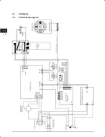
Page 18: ...16 DE 14 Schaltplan 14 1 Klemmenbelegungsplan...

Page 19: ...Dokumentenhistorie 2008 04 Erstausgabe 2010 01 Redaktionelle nderungen Erg nzung Dokument EG Konformit tserkl rung 2011 11 Neues Layout Redaktionelle nderungen Erg nzung Kapitel 15 Service 2014 01 Re...

Page 20: ......

Page 21: ...n filter disc flash lamp and chip card 8 7 6 Checking the machine 9 7 6 1 Control panel 9 7 6 2 Drawer for polymerisation products 9 7 6 3 Filter drawer 10 7 6 4 Inside the machine 10 8 Appliance 10 8...

Page 22: ...ation of the machine Type of machine Valid from Serial number Light polymerisation device HiLite power 2017 07 0001 ff 1 3 EU Statement of conformity Herewith we Kulzer GmbH Leipziger Stra e 2 63450 H...

Page 23: ...ased on the operating manual and written in light of the work to be performed 2 4 Unit diary Operating manual We recommend that you keep a machine diary and document all tests and major work e g servi...

Page 24: ...n working with the unit CAUTION If particular problems not described in detail in this operating manual arise please contact the supplier to ensure your own safety 3 1 Working rules CAUTION Remove any...

Page 25: ...l panel 5 Filter 6 Drawer for filter 7 Maintenance flap 2 Light reflector 3 Object holder 4 Drawer for polymerisation goods 8 LED status control 11 90 second button intermediate polymerisation 12 180...

Page 26: ...view with maintenance flap being opened 13 Flash lamp with reflector 14 Chip card 5 3 Rear view 15 Power switch 16 Voltage selector 17 Plug for non heating apparatus with fuses 18 Rating plate 1 4 6...

Page 27: ...tal position Avoid jerking it For sizes and weight see paragraph 13 Technical Data 7 2 Installation The HiLite power unit must be placed on a solid fire resistant surface in a way to ensure a safe hor...

Page 28: ...nd the respective chip card for the lamp To open the maintenance flap loosen the self captivating plug locking screws lift the maintenance flap and remove it Insert filter disc into notch 19 Filter di...

Page 29: ...teps described above CAUTION Please observe the following information When exchanging the flash lamp the chip card must also be exchanged In the case of complaint the flash lamp must always be sent ba...

Page 30: ...ventilator must cool the prosthetic material evenly and well to ensure an excellent polymerisation result This will only happen if the product is positioned in the centre Observe the following inform...

Page 31: ...e it if contaminated 8 2 Errors and how to eliminate those DISCONNECT FROM MAINS Risk of fatal injury Unplug the unit before opening it ELECTRIC SHOCK Danger of electric shock when unit is opened Erro...

Page 32: ...t and clean it if required or position objects in a better way Bottom of the reflector pot is bent and blocks the fan motor Check reflector pot if required align bottom or replace pot Defective fan Re...

Page 33: ...at least once a month with a soft lint free cloth to clean it DISCONNECT FROM MAINS Risk of fatal injury Unplug the machine before working on it NOTE Dirt on the flash lamp will considerably reduce i...

Page 34: ...with a flash lamp HOT SURFACE When the machine has been in operation only a short time the flash lamp and lamp reflector get very hot and can burn you if you touch them See the diagram on the machine...

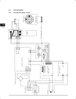
Page 35: ...evices contact your dealer or Kulzer subsidiary in your country CAUTION Marked equipment must not be brought to local waste disposal centres 13 Technical Data 13 1 Mains connection Value Unit Nominal...

Page 36: ...16 GB 14 Circuit diagram 14 1 Terminal allocation scheme...

Page 37: ...16 Document history 2008 04 First edition 2010 01 Text editing input of EC Declaration of Conformity document 2011 11 New Layout Text editing update paragraph 15 Service 2014 01 Text editing update pa...

Page 38: ......

Page 39: ......
Page 40: ...W17742 DE GB 66050251 11 2017 07 Manufacturer Kulzer GmbH Leipziger Stra e 2 63450 Hanau Germany...

Reviews: