- 14 -
GB
DE
GB
FR
ES
IT
PT
NL
SE
DK
NO
FI
GR
DISCONNECT FROM MAINS
Unplug the machine before working on it.
The end user can replace the following parts:
Lamp reflector with flash lamp
Chip card
Filter disc
Light reflector
Filter
CAUTION
You do not have to disassemble the housing to do the work listed above!
If more comprehensive repairs are required, send the machine to the manufacturer!
Please contact the relevant country office or regional Kulzer service partners!
See paragraph 15 Service.
NOTE
Before replace one of these parts, check whether its reduced performance is due to dirt. For the cleaning intervals
see paragraph 9 Cleaning.
10.2 Repair
ELECTRIC SHOCK
Caution electric shock!
Risk of fatal injury if instructions are not followed.
Observe the following information:
DISCONNECT FROM MAINS
Unplug the machine before working on it.
10.3 Changing the lamp reflector with a flash lamp
HOT SURFACE
When the machine has been in operation only a short time, the flash lamp and lamp reflector get very hot and
can burn you if you touch them. See the diagram on the machine!
Observe the following information:
Before changing the flash lamp let the machine cool down for approx. 30 minutes.
NOTE
Instructions for exchanging the flash lamp see parapraph 7.5 Installation filter disc, flash lamp and chip card.
10.4 Changing the filter disc
The filter disc can only be exchanged after removing the flash lamp. Remove the filter disc and replace it with a new one.
The upper and underside of the filter disc are identical so that incorrect mounting is avoided. Cleanliness must be ensured.
11 Disposal
Recyclable materials are used to manufacture the light polymerisation device HiLite
®
power. These do not present any particular
or unusual dangers for disposal. Kulzer GmbH is naturally willing to go beyond its legal obligations and take back used machines.
The machine is designed for a service life of approx. 10 years.
Summary of Contents for HiLite power
Page 1: ...DE Betriebsanleitung GB Operating instructions HiLite power DE GB...
Page 2: ......
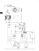
Page 18: ...16 DE 14 Schaltplan 14 1 Klemmenbelegungsplan...
Page 20: ......
Page 36: ...16 GB 14 Circuit diagram 14 1 Terminal allocation scheme...
Page 38: ......
Page 39: ......


