20
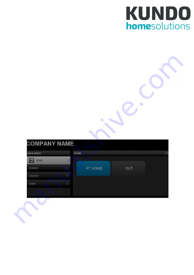
There are 2 scenes in this diagram. All scenes have a clapper board
icon and those that have configured schedule or event triggers have
a clock superimposed on the icon. Security Scenes have a bell su-
perimposed on the icon. The turning wheel at the top right indicates
that the scenes are updating their status. Scene status is updated
only when Home or Scenes buttons are clicked, or when a scene is
triggered. Clicking on a scene triggers it manually, turning its tab blue
and starting the status update. If for some reason, it is not activated,
it returns to its original color. As the same devices may be activated
by multiple scenes, triggering 1 scene may affect the state of multiple
scenes. The “Toggle View” button, only on the Tablet UI, can switch
the scenes arrangement to columns and rows, instead of just 1 col-
umn.
Figure 7: PC-UI - Scene Toggle
6.2.2 Scenes
The Scenes page looks the same as Home page except for a ‘New
Scene’ that allows scene creation and that clicking on a scene allows
viewing and editing it.
Summary of Contents for Central Home Unit
Page 1: ...Central Home Unit Manual...
Page 48: ...46 6 3 5 4 Alarm Notification Figure 48 Eng UI Alarm Notification...
Page 49: ...47 6 3 5 5 Meter Figure 49 Eng UI Meter 6 3 5 6 Battery Figure 50 Eng UI Meter...
Page 52: ...50 6 3 5 11 Door Lock Figure 55 Eng UI Door Lock...
Page 66: ...64 gers scenes can be chosen Figure 72 Eng UI Security Scene Edit...


