background image

14

Service Manual Series 634

For internal use only

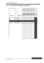
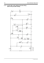
5.3.2

Control without setting a time on filling 
(Static without circulating)

Filling until the filling switch f1 activates the operating mechanism motor m1..

St

rom

p

fad

Summary of Contents for 634 Series

Page 1: ...a y y k NKL a_ NNQFJ a_ NMQFJ a_ NLLFJ a_ NKLFJ...

Page 2: ...ice Manual H7 410 02 03 Responsible D Rutz K PPERSBUSCH HAUSGER TE AG Email dieter rutz kueppersbusch de Tel 0209 401 733 Kundendienst Fax 0209 401 743 Postfach 100 132 Date 22 07 2003 45801 Gelsenkir...

Page 3: ...deposits 28 7 6 Starch deposits 28 7 7 Check list Results after washing 29 7 8 Water soluble deposits or deposits of regenerating salt on the dishes 30 7 9 Discolouration colour deposits 30 7 10 Resi...

Page 4: ...fore commencing with any repair work Should tests under electrical tension be necessary always use an earth leakage circuit breaker Always ensure that the protective conducter connection is carried ou...

Page 5: ...min 2H is indicated on the display If the time setting has been set the number will appear on the display with a small h The programm duration will automatically be adjusted in accordance with the typ...

Page 6: ...carried out in the bottom basket until the required temperature has been reached Consumption data Gentle 40 This program comprises cleaning at 40 an intermediate rinse rinsing with a rinsing agent at...

Page 7: ...temperature by 3 K in the rinse program with a rinsing agent 3 4 3 Program interruption reset With the appliance switched on press the Normal 65 button and the next button but one for 3 sec A 0 appea...

Page 8: ...iances screw the appliance in an upward direction by means of the adjustable feet until the outer casing is at the same level as the working top 4 2 Water connection If the appliance is installed onto...

Page 9: ...a switch lever which then switches off the filling and safety valve electrically At the same time the discharge pump is switched on the rinse water is removed from the rinsing container and the discha...

Page 10: ...which is connected in series and switches off at 85 C This temperature control is combined with an NTC sensing element negative temperature coefficient comprising one component part The surface of th...

Page 11: ...perature safety switch applied 85 C is combined with the NTC sensing element for the programs In the case of a defect the heater is switched off when the water temperature reaches 85 C impulse 5 2 8 N...

Page 12: ...is activated by the electronics system and is located on the water softening device In the case of naturally soft water which has no negative effects on glass the softening can be set onto 0 and the g...

Page 13: ...Service Manual Series 634 13 For internal use only 5 3 Filling procedures 5 3 1 Control without setting a time on filling Static filling dynamic filling...

Page 14: ...ice Manual Series 634 For internal use only 5 3 2 Control without setting a time on filling Static without circulating Filling until the filling switch f1 activates the operating mechanism motor m1 St...

Page 15: ...ice Manual Series 634 15 For internal use only 5 3 3 Control without setting a time on filling Dynamic without circulation m2 Filling until the filling switch f1 activates the operating mechanism moto...

Page 16: ...16 Service Manual Series 634 For internal use only 5 3 4 Control without setting a time on dynamic filling current path F Filling H Heating R Rinsing agent added P Pumping...

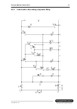
Page 17: ...Service Manual Series 634 17 For internal use only 5 3 5 Control without a time setting on dynamic filling Time in sec Process...

Page 18: ...18 Service Manual Series 634 For internal use only 5 3 6 Control with a time setting on dynamic filling Static filling dynamic filling Strompfad current path...

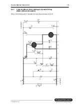
Page 19: ...4 19 For internal use only 5 3 7 Control without a time setting on dynamic filling Static without circulation Filling until the filling switch f1 activates the operating mechanism motor m1 Strompfad c...

Page 20: ...with a time setting on dynamic filling Dynamic with circulation m2 Filling until the filling switch fl activates the operating mechanism motor m1 Should however the filling switch not switch on the co...

Page 21: ...Service Manual Series 634 21 For internal use only 5 3 9 Control with a time setting on dynamic filling ccurrent path...

Page 22: ...22 Service Manual Series 634 For internal use only 5 3 10 Control with a time setting on dynamic filling...

Page 23: ...nual Series 634 23 For internal use only 5 3 11 Control with a time setting on dynamic filling Temperature gauging point crossed Step time approx 4 seconds Switch can be opened or closed OFF Process T...

Page 24: ...25 140 130 72 20 31 2K on cleaning 19 3 Power consumption in kWh 1 6 1 45 1 05 0 8 0 6 0 1 Water consumption in litres without activated aqua sensor 21 18 18 12 15 12 10 4 Aqua sensor activated yes no...

Page 25: ...es in order to check Pump is making a buzzing noise Pump is mechanically blocked bloc kage or damage to the pump Clean the pump above the impeller If neces sary remove the pump Pump is not working See...

Page 26: ...ing or insulation faults of the consuming device Poor electrical connection or leakage paths on electrical component parts pay attention to the edge connector Advise the customer Observe safety instru...

Page 27: ...r Replacing the module will at present not result in any remedy The plug repair set Mat No 26 6753 can be used for defect connections to electrical controls Customer s information Cause Remedy Calcare...

Page 28: ...little water in the appliance pay attention in the case of alternating rinse technology intervals of approx 1 min Non return flap leaking dirty water flows back into the appliance Rinsing in the botto...

Page 29: ...ished Insufficient cleaning agent used Discoloration of plastic caused by tomato deposits tea coffee etc Cleaning agent very lumpy cleaning effect and dissolving properties deteriorating Weak program...

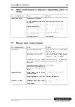
Page 30: ...spenser or in the cutlery basket Spray arm nozzles blocked sieves not properly engaged Dispenser device blocked from spray large pot or similar object placed on the left side Check draining non return...

Page 31: ...t dishwasher compatible knife knife blade steel is usually less rust resistant Very thick film of rust caused by corrosive dishes or dish baskets Optimise the setting subsequent to testing Advise the...

Page 32: ...the rinsing agent has dissolved too soon Dishes which do not dry easily Advise the customer Advise the customer point out the function of the heat exchanger and if necessary connect the appliance to...

Page 33: ...rn the pump to the right picture on the right The pump can then be pulled off Assembly is carried out by means of a reverse procedure Prior to installment it is advisable to use dishwashing liquid so...

Page 34: ...F1 level switch UB Upper basket rinse DB Double basket rinse HP Heating plus temperature increase of 2 C CW Cold water WW Warm water a1 Main switch e0 Integrate door switch e2 3 Reed switch e6 Float s...

Page 35: ...me mit Entst rung Interference suppression terminal Kondensatormotor Capacitor motor Kupplung Coupling Laugenpumpe Drain pump Magnetventile Magnetic valves Modul Module Niveaudruckdose Level gauge PTC...

Page 36: ...pressed and activate the main switch As long as the buttons S2 to S5 remain pressed the LEDs L2 to L5 will flash Subsequent to releasing the buttons S2 to S5 the current coding will be indicated as a...

Page 37: ...ill light up when one of the program buttons is pressed On pressing the S3 button the fault indicators and the end LEDs will also light up The customer service program is started when the S2 and S4 bu...

Page 38: ...38 Service Manual Series 634 For internal use only 9 3 Circuit diagrams IG 634 2...

Page 39: ...Service Manual Series 634 39 For internal use only...

Page 40: ...t coding will be indicated as a code on the display see code chart 2 Setting variants By pressing the S2 button the various variant codes can be set see chart 3 Storing the code On switching off the a...

Page 41: ...ed No pre set time is possible and the customer service special program ends when the main switch is switched off The fault number is indicated on the display 1 Aqua sensor defect Attention Indicator...

Page 42: ...42 Service Manual Series 634 For internal use only 9 6 Circuit diagrams IG 644 2...

Page 43: ...Service Manual Series 634 43 For internal use only...

Page 44: ...he LEDs L2 to L5 will flash Subsequent to releasing the buttons S2 to S5 the current coding will be indicated as a code on the display see code chart 2 Setting variants By pressing the S2 button the v...

Page 45: ...The fault number is indicated on the display 1 Aqua sensor defect Attention indicator even if there is no aqua sensor 2 Heating fault 3 Fault combination of fault 1 fault 2 4 Filling fault 5 Fault com...

Page 46: ...46 Service Manual Series 634 For internal use only customer service test program only...

Page 47: ...Service Manual Series 634 47 For internal use only 9 9 Circuit diagrams IG 669 2...

Page 48: ...48 Service Manual Series 634 For internal use only...

Page 49: ...Service Manual Series 634 49 For internal use only 9 10 Circuit diagrams IG 659 2...

Page 50: ...50 Service Manual Series 634 For internal use only...

Page 51: ...Service Manual Series 634 51 For internal use only 9 11 Circuit diagram S0 60 0488 IG 659 2 dependis on version...

Page 52: ...52 Service Manual Series 634 For internal use only 9 12 Circuit diagram S0 60 0489...

Page 53: ...on the appliance an identification of the variant coding will be shown in the case of a successful overlap contact interrogation e g 20 Variant 0 21 Variant 1 and so on The respective LED will light u...

Page 54: ...is positioned for the bottom basket The next step in the program can be started when the S3 button is activated Exception in the filling stage it is only possible to continue to the next stage by mea...

Page 55: ...mal rinse drying phase Program symbols Intensive 70 Fast 70 Soaking Upper basket Normal 65 C Gentle 40 Time reduction Lower basket ECO 50 Pre rinse Time pre selection Display Sa Sb S1 S2 S3 S4 S5 S5 0...

Page 56: ...56 Service Manual Series 634 For internal use only 9 15 Circuit diagram S0 60 0523 according to equipment...

Page 57: ...Service Manual Series 634 57 For internal use only 9 16 Circuit diagram S0 60 0546 according to equipment...

Page 58: ...iance an identification of the variant coding will be shown in the case of a successful overlap contact interrogation e g 20 Variant 0 21 Variant 1 and so on The respective LED will light up when one...

Page 59: ...circuit 9 Fault combination of fault 1 fault 8 10 Fault combination of fault 2 fault 8 16 Water diverter cannot be positioned If neither of the two buttons Sa Sb is selected alternating rinsing is se...

Page 60: ...60 Service Manual Series 634 For internal use only 9 18 S0 60 0540 IGV 659 2...

Page 61: ...Service Manual Series 634 61 For internal use only 9 19 Circuit diagrams S0 60 556...

Page 62: ...ent to a successful overlap contact interrogation e g 20 Variant 0 21 Variant 1 and so on The respective LED will light up when one of the program buttons is pressed On pressing the S3 button the disp...

Page 63: ...s selected the water diverter is positioned for the lower basket The next step in the program can be started when the S3 button is activated If the heating stage is skipped a heating fault will be ind...

Page 64: ...rmance no drying phase Program symbols Intensive 70 Fast 35 Soaking Upper basket auto 55 65 Gentle 40 Time reduction Bottom basket ECO 50 Pre rinse Pre set time D Sa Sb M lock E RA S1 S2 S3 S4 S5 S6 0...

Reviews: