54
Service Manual Series 634
For internal use only
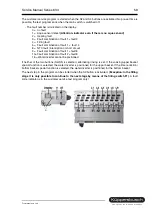
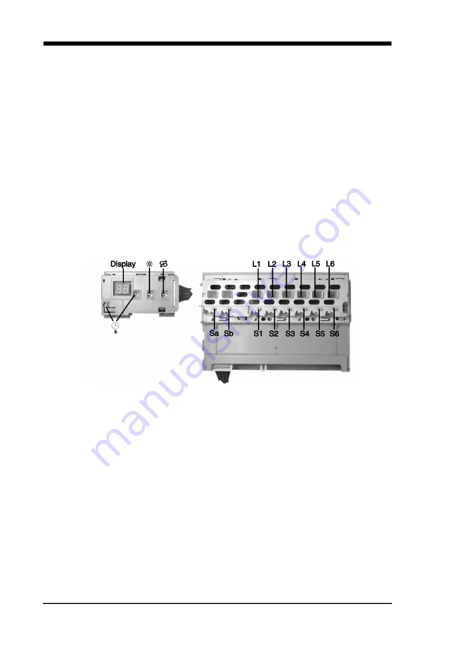
The customer service program is started when the S2 and S4 buttons are activated. No pre-set time is
possible, the test program ends when the main switch is switched off.
- The fault number is indicated on the display:
0 = no fault
1 = Aqua sensor defect
(Attention: indicator even if there is no aqua sensor!)
2 = Heating fault
3 = Fault combination of fault 1 + fault 2
4 = Filling fault
5 = Fault combination of fault 1 + fault 4
8 = NTC fault (interruption or short circuit)
9 = Fault combination of fault 1 + fault 8
10= Fault combination of fault 2 + fault 8
16 = Water diverter cannot be positioned
If neither of the two buttons (Sa/Sb) is selected, alternating rinsing is set. If the soaking/upper basket
special function is selected, the water diverter is positioned for the upper basket. If the time reduction/
bottom basket special function is selected, the water diverter is positioned for the bottom basket.
The next step in the program can be started when the S3 button is activated.
(Exception: in the filling
stage it is only possible to continue to the next stage by means of the filling switch F1)
. A fault
code indicator is in the customer service test program only!
9.14
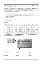
Coding instructions for an electronics system with G controls
(IG 644.2)
Subsequent to the replacement of the standard electronic control mechanisms installed, the control
system must once again be coded to comply with the appliance programs (see chart).
Attention: In the case of appliances with 4 or 5 programs/buttons, the control system must be
programmed prior to fitting the panel cover.
1.
Instructions:
Press the buttons S2, S3, S4 and S5 simultaneously, keep them pressed and activate the main
switch. As long as the S2 to S5 buttons remain pressed, the LEDs L2 to L5 will flash.
Subsequent to releasing the buttons S2 to S5, the current coding will be indicated as a code on the
display (see code chart).
2.
Setting variants:
By pressing the S2 button the various variant codes can be set (see chart).
Summary of Contents for 634 Series
Page 1: ...a y y k NKL a_ NNQFJ a_ NMQFJ a_ NLLFJ a_ NKLFJ...
Page 38: ...38 Service Manual Series 634 For internal use only 9 3 Circuit diagrams IG 634 2...
Page 39: ...Service Manual Series 634 39 For internal use only...
Page 42: ...42 Service Manual Series 634 For internal use only 9 6 Circuit diagrams IG 644 2...
Page 43: ...Service Manual Series 634 43 For internal use only...
Page 46: ...46 Service Manual Series 634 For internal use only customer service test program only...
Page 47: ...Service Manual Series 634 47 For internal use only 9 9 Circuit diagrams IG 669 2...
Page 48: ...48 Service Manual Series 634 For internal use only...
Page 49: ...Service Manual Series 634 49 For internal use only 9 10 Circuit diagrams IG 659 2...
Page 50: ...50 Service Manual Series 634 For internal use only...
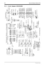
Page 52: ...52 Service Manual Series 634 For internal use only 9 12 Circuit diagram S0 60 0489...
Page 60: ...60 Service Manual Series 634 For internal use only 9 18 S0 60 0540 IGV 659 2...
Page 61: ...Service Manual Series 634 61 For internal use only 9 19 Circuit diagrams S0 60 556...


