background image

Service Manual

21

For internal use only

6.4

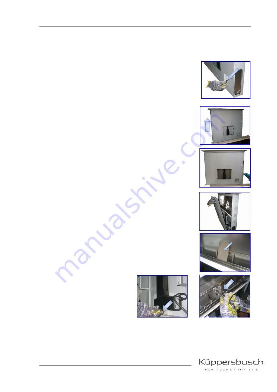
Replace the actuator

Remove the suctioning unit or the pipe flange in case of external motor version (see “Check if the
red power button is in on position” on page 5).

Disconnect the connectors in the downdraft lower panel.

Remove the downdraft from the cabinet.

Remove the body front panel.

Remove the actuator connection cover.

Remove the actuator screw placed in the lower side, by using two
17mm spanners.

Unscrew the screw placed in the
upper side.

Summary of Contents for EDD 9660.0

Page 1: ...Down Draft cooker hood EDD 9660 0 Problems and solutions ...

Page 2: ...e Manual H5 51 01 Responsible U Laarmann KÜPPERSBUSCH HAUSGERÄTE AG E mail uwe laarmann kueppersbusch de Tel 0209 401 732 Customer Service Fax 0209 401 743 Postfach 100 132 Date 28 11 2013 45801 Gelsenkirchen ...

Page 3: ... Replace the body liner 17 5 The extractable unit opens but the suctioning system does not work at any speed 19 5 1 Check if the 6 pole suctioning unit connector 19 5 2 Replace the main electrical system board 19 5 3 Replace the suctioning unit if the downdraft is equipped with an internal motor 19 5 4 Replace the external sem power pack 19 6 The suctioning system works but the extractable unit do...

Page 4: ...al current circuit breaker must always be used The earthed conductor resistance may not exceed the resistance specified in the standard It is vital for ensuring the safety of persons and the functioning of the appliance On completion of repairs an inspection must be carried out in accordance with VDE 0701 Association of German Electrical Engineers or the corresponding regulations for your country ...

Page 5: ...e red power button is in on position Disconnect power supply by pressing the red button in the electrical system box Release the movable connector wires by removing the black sheath Check if the connector inner contacts are inserted properly with the help of a screwdriver Carry out this check in both the movable and the fixed connectors Attention Connecting the appliance to the mains and repairing...

Page 6: ...CK Magnetic safety circuit breaker PIN 4 YELLOW PIN 7 GREY Actuator PIN 9 BROWNN PIN 8 BLUE Ground connection PIN 5 YELLOW GREEN SCHWARZ GELB GRAU BLAU ROT ERDE Tasten für die Anwesen heit der Fettfilter Magnetischer Leitungsschutzschalter BLACK YELLOW GREY BLUE RED ERDE Grease filters panel presence button Magnetic safety circuit breaker YELLOW GREEN BROWN ...

Page 7: ...he grease filters covering panel which in case of malfunctioning prevent the downdraft from starting any functions Lift the extractable downdraft unit up by pressing the on off key Remove the grease filters covering panel Remove le right and left hinge covers by pulling outwards By using a multimeter and in the continuity mode check if the button is working properly ...

Page 8: ...d in the electrical system box If the button must be replaced it is necessary to use an original spare part 2 5 Check if the panel is unhooked If the extractable unit is closed and the panel accidentally unhooks causing the opening of the contact of the filters panel position it is necessary to hook it again in order to restore operation Disconnect the downdraft from the power supply Button releas...

Page 9: ...d the push button cable C Remove the brackets which fix the downdraft to the cabinet In case of internal motor version remove the motor fixing screws and remove the suctioning unit In case of external motor version EM remove the air outlet flange Lift the downdraft up from the cabinet A B C ...

Page 10: ...ously on both sides of the panel After having remounted the body front panel and before placing the downdraft again into the cabinet we recommend to check the downdraft operation 2 6 Replace the electrical system board Disconnect power supply Remove the electrical system box cover Find the main board box ...

Page 11: ...r screws Remove the fairlead Disconnect the connectors one by one paying special care in reconnecting them properly in the new board 2 7 Replace the power supply electrical board Disconnect power supply Remove the electrical system box cover Find the main board box ...

Page 12: ...ing Check if the push button grey connector in the connectors panel is inserted properly and if there are any bent pins inside the connector Check if the push button flat cable inside the electrical system box is connected properly to the main board Check if the flat cable inside the right column of the extractable unit is connected properly to the connector In order to do this operation it is nec...

Page 13: ...he inner contacts of the fixed connector placed in the electrical system box as well as the movable connector found in the suctioning unit are all inserted properly Open the electrical system box and check if the suctioning unit connections in the green connector are correct 3 2 Check if the suctioning unit 6 pole connector wires in the electrical system board are connected properly For internal m...

Page 14: ...ternal motor EM version check the connections accordingly to the following diagram In case of connection with sem external power packs make sure that the 7 m cable used to connect the cooker hood to the external motor is not cut or damaged tempered ...

Page 15: ... For internal use only Check the connections in such a case To be connected to the downdraft Length 7m connection External motor without SEM External motor with SEM To be connected to the downdraft Length 7m connection ...

Page 16: ...r internal use only 3 3 Replace the suctioning unit in case of internal motor version Disconnect power supply Disconnect the 6 pole cable from the suctioning unit Dismount the suctioning unit and replace it with a new one ...

Page 17: ...allation manual 4 The stainless steel body liner is damaged 4 1 Replace the body liner Disconnect the downdraft from power supply Remove the brackets which fix the downdraft to the cabinet In case of internal motor version remove the motor fixing screws and remove the suctioning unit In case of external motor version EM remove the airoutlet flange Attention Never cut the connecting cable during in...

Page 18: ...actable unit up Remove the upper front panel Disconnect the flat cable Remove the body liner fixing screws placed in the rear and lateral side Before removing the body liner from the extractable unit we recommend to use protective adhesive paper in order to avoid the extractable unit to be scratched Remove the body liner ...

Page 19: ...draft is equipped with an internal motor See Replace the suctioning unit in case of internal motor version on page 16 5 4 Replace the external sem power pack if the downdraft is equipped with an external motor See chapter Replace the sem external power pack in case of external motor em version on page 17 6 The suctioning system works but the extractable unit does not open 6 1 Check if the electric...

Page 20: ...erly and that pins inside the connector are crimped properly 6 3 Check if the electro mechanic transformer placed inside the electrical system box is working properly Remove the electrical system box cover Find the electro mechanic transformer Check if 12V are in the electro mechanic transformer secondary Carry out the same test in the CN102 and CN103 connectors in the main electrical system board...

Page 21: ...on see Check if the red power button is in on position on page 5 Disconnect the connectors in the downdraft lower panel Remove the downdraft from the cabinet Remove the body front panel Remove the actuator connection cover Remove the actuator screw placed in the lower side by using two 17mm spanners Unscrew the screw placed in the upper side ...

Page 22: ...ol panel does not light up 7 1 Check if the connector is connected properly 7 2 Check if the connector inside the extractable unit column is connected properly Remove the upper front panel and check if the connector is inserted properly 7 3 Check if the flat cable inside the main board is connected properly ...

Page 23: ...of stainless steel front side version it is possible to replace only the push button panel As for the glass version it is necessary to remove the front panel by unscrewing the two side screws Disconnect the flat cable connector of the push button panel Unscrew the two dowels which fix the push button bracket Remove the push button support Remove the push button stainless steel cover Remove the pus...

Page 24: ...g does not light up 8 1 Replace the neon lamp tube Remove the upper front panel Disconnect the flat cable Remove the neon tube and replace it with a new one Remount the upper front panel and reconnect the flat cable then check the neon tube operation ...

Page 25: ...ly Carry out an electric continuity test between the neon tube holders and the ballast inside the electrical system box Place a test prod in one of the neon tube holders contacts and check the ballast continuity inside the electric system box Carry out the same test in all the four ballast prods 8 3 Replace the neon tube supports In case one of the neon tube support is broken it is necessary to re...

Page 26: ...emove the component by moving it downwards 8 4 Replace the ballast Disconnect the ballast wires by using a screwdriver and pushing on the side shown in the figure Remove the fixing screws and replace the ballast with a new one 8 5 Replace the main electrical system board See Replace the electrical system board on page 10 8 6 Replace the Touch control See Replace the push button panel on page 23 ...

Page 27: ...or internal use only 9 Configuration of the remote control Procedure Please proceed as follows 1 Press button 3 or 4 until symbol appears 2 Press button g and keep hold for 5 seconds 3 The remote control is now configured ...

Reviews: