background image

6. Changing and setting the burner injectors

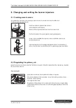
6.1 Cooking zone burners

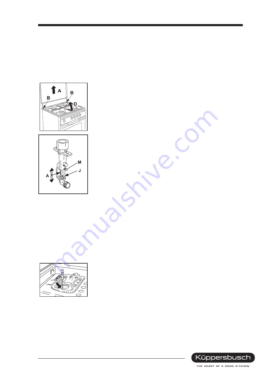
To replace the injectors of the cooking zone burners, the cooker hob must be lifted out.
To this end proceed as follows:

Pull cover plate A upwards and remove.

Undo screws B with holders.

Remove ribbed grid and burners from the cooker hob.

Pull hob forwards, lift up and position leaning backwards.

Loosen the screw of the injector carrier and lift the tube for air
control right out.

Unscrew injector with a polygonal spanner (size 7) and replace it
with an injector which is prescribed for the gas being used (see table).

6.2 Regulating the primary air

Ignite the burner and check whether the flame is regular. Should an adjustment be necessary, regulate
the air with the tube A.

Oven and grill

Ignite the burner and check whether the flame is regular.

Should an adjustment be necessary, move the bushing until you have
found the correct setting.

Then tighten the screw.

Regulation of the primary air is exactly right when there is enough safety
against flame lift when the burner is cold and against light-back when the
burner is hot.

Technical manual GH 606.0 E/GH 506.0 E/GH 505.0 E/GKH 507.0 E

19

For internal use only

Summary of Contents for GH 505.0 E

Page 1: ...Gas cookers GHK 606 0 E GHK 506 0 E GHK 505 0 E GKH 507 0 E GB...

Page 2: ...Technical manual H2 120 61 01 Responsable Kirchmaier K ppersbusch Vertriebsges mbH Tel 0209 401 718 Kundendienst Fax 0209 401 743 Postfach 100 132 Date 27 07 1998 45801 Gelsenkirchen...

Page 3: ...s 15 3 6 Functional check 15 3 7 Installing the appliance 15 4 General technical information 16 5 Injector tables 18 6 Changing and setting the burner injectors 19 6 1 Cooking zone burners 19 6 2 Regu...

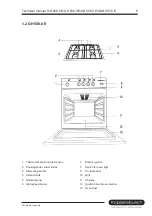
Page 4: ...immering burner 8 Thermostat control knob for oven 3 Aeration slits 9 Control panel 4 Normal burner 10 Grill 5 High speed burner 11 Shelves 6 Switch for oven light 12 Ignition hole for oven burner 13...

Page 5: ...one control knobs 8 Switch for oven light 3 Simmering burner 9 Control panel 4 Aeration slits 10 Grill 5 Normal burner 11 Shelves 6 High speed burner 12 Ignition hole for oven burner 13 Oven door Tech...

Page 6: ...ner 2 Cooking zone control knobs 7 Switch for oven light 3 Simmering burner 8 Control panel 4 Aeration slits 9 Shelves 5 Normal burner 10 Ignition hole for oven burner 11 Oven door 6 Technical manual...

Page 7: ...ctor switch 3 Aeration slits 11 Control panel 4 Normal burner 12 Top heat 5 High speed burner 13 Grill 6 Pilot light yellow 14 Hot air fan 7 Heating light red 15 Shelves 8 Cooking zone control knobs 1...

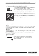
Page 8: ...8 290 C 2 1 2 Switch symbols and modes OFF Lighting Always switch on when the oven is being used 1 8 Temperature settings of the top bottom heat Always only use one shelf level The oven is fitted wit...

Page 9: ...ensils Baking tins As the baking tins are not supposed to protrude over the edge of the grid only place them in the centre of the roasting grid Position rectangular baking tins at right angles to the...

Page 10: ...ting Always switch on when the oven is being used 1 8 Temperature settings of the top bottom heat Always only use one shelf level Grilling Suitable for small amounts of food to be grilled The oven is...

Page 11: ...rilling is produced on the steel grid To ignite press the thermostat control knob for the oven slightly and turn clockwise into the position Grill Activate the electric ignition with the pushbutton Af...

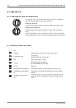
Page 12: ...ched 2 3 2 Switch symbols and modes OFF Lighting Always switch on when the oven is being used Top bottom heat Pre heating Baking biscuits and moist cakes Grill Grilling flat pieces of meat Cold air Wi...

Page 13: ...no details for hot air Important With cakes with a moist layer of fruit the development of moisture is particularly great Max two cakes should be baked at the same time Top bottom heat Pre heat and b...

Page 14: ...ection pressure ranges 18 to 25 mbar for gases in the 2nd family 42 5 to 57 5 mbar for gases in the 3rd family The appliance must not be operated outside the above mentioned pressure ranges The heat l...

Page 15: ...steady flame If necessary change the air setting 3 7 Installing the appliance After removing the packaging carefully check whether the appliance has been damaged Remove the packaging and protective fi...

Page 16: ...l burner A 2 x 1 9 kW 2 x 1 81 kW 2 x 1 81 kW 2 x 1 81 kW Simmering burner H 1 x 1 0 kW 1 x 0 99 kW 1 x 0 99 kW 1 x 0 99 kW Oven Gas 3 7 kW Gas 3 13 kW Gas 3 13 kW Electric BH 1 1 kW TH 0 9 kW Hot air...

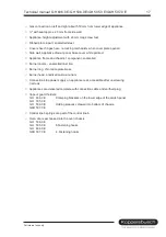
Page 17: ...te brass Burner head anodised cast aluminium Connection strip power supply on appliance rear accessible after unscrewing 3 screws Appliances are delivered complete with connection cable and earthed pl...

Page 18: ...80 72 34 4 125 E 3 140 E 5 Oven High setting Low setting 3 130 0 770 75 40 max 130 E N5 146 E 5 Grill High setting 2 310 68 max 120 5 130 3 GH 505 0 E LPG Hs 125 81 MJ m 50 mbar Injector 1 100mm Space...

Page 19: ...ner size 7 and replace it with an injector which is prescribed for the gas being used see table 6 2 Regulating the primary air Ignite the burner and check whether the flame is regular Should an adjust...

Page 20: ...correct low setting see Gas flow setting table This setting only applies to natural gas For LPG the screw must be tightened against the stop 6 4 Oven burner Raise and remove the bottom plate above th...

Page 21: ...el at front and back Remove side panel 3 Dismantling appliance drawer panel Remove panel by undoing 4 screws on the appliance drawer inside 4 Dismantling switch panel Pull off control knob Undo 2 scre...

Page 22: ...en door Grip the oven door with both hands at the sides and push the hinges into the relevant openings in the oven Slowly close the oven door completely Flap down the brackets on the door hinges and c...

Page 23: ...ff lower holding strip of the door pane 2 by unscrewing the 3 fastening screws 2a and lift off the front pane c Dismantling hinges Dismantle front pane as described then take off the hinges 3 after re...

Page 24: ...nurled screws each Press in nuts in the chassis GKH 507 0 E c Oven door seal The door seal is provided with holding lugs Replacement and assembly by lengthening the seal slightly and hooking it out or...

Page 25: ...the new gas tap After changing the gas tap it is imperative to conduct a leak test at the connection to the gas float 5 and union nut 3 d Oven thermostat Perform dismantling and assembly as for the ga...

Page 26: ...Dismantle by pressing the sparks plugs 1 down and turning them Pull ignition cable 2 off the transformer Install by pushing up from below and pressing on the spring 3 from above Attach ignition cable...

Page 27: ...trol knob 1 off Undo thermostat holding screws 2 from the front Pull double capillary tube sensor 3 above the flange of the top heat and on the left of the hot air heater out of the holding clips 4 Pu...

Page 28: ...rill Unscrew oven rear Detach cable from heater 1 Undo screws 2 from the appliance rear Remove heater from the oven Assemble in reverse sequence middle connections grill outer connections top heat g B...

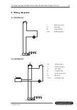
Page 29: ...Terminal block T0 T3 Earthing system 9 2 GH 606 0 E PA Switch ignition I Switch oven light LF Oven light M Terminal block A Ignition transformer CA Electrode T0 T3 Earthing system Technical manual GH...

Page 30: ...I Switch oven light LF Oven light M Terminal block A Ignition transformer CA Electrode CAF Oven electrode CAG Grill electrode T0 T3 Earthing system 30 Technical manual GH 606 0 E GH 506 0 E GH 505 0 E...

Page 31: ...ectrode CAF Oven electrode CAG Grill electrode T0 T3 Earthing system C Top heat G Grill H Hot air heater S Bottom heat E1 Oven thermostat F1 Oven selector switch TL Temperature protection fuse S2 Cont...

Reviews: