background image

Service Manual IW 1209.0W / IWT 1259.0W

81

For internal use only

14.4 Diagnostic Programme - Drying

This diagnostic programme provides a semi-automatic check of all components used by the machine
during the drying programmes.
Accessing the Diagnostic Programme

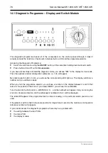
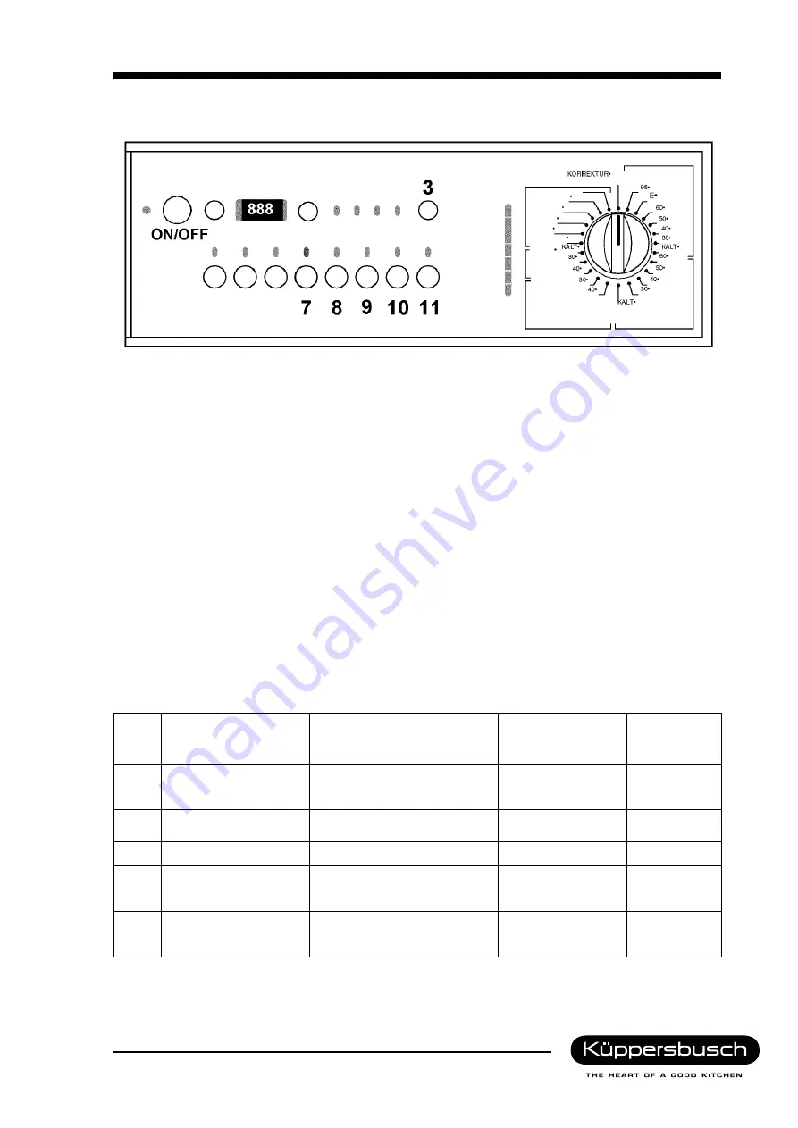
Switch the machine on using the

ON/OFF

button, at the same time holding down buttons

8

and

10

.

Press buttons

7

and

9

within

five seconds

.

If you have successfully activated the diagnostic mode, you will see

"t04"

in the display for 3 seconds.

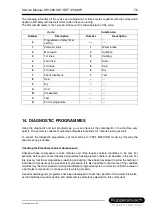
The diagnostic programme is subdivided into individual programme phases; one or more components
can be tested during each phase. It is possible to exit certain of the phases before completion by
pressing the

11

button.

All of the fault code functions are active and are displayed during each phase.
Press button

3

to view a number of variable parameters. First, the parameter reference appears briefly

(PO1, PO2 etc.), then its value.

P1:

Water level (mm)

P2:

Condition of safety pressure switch 1(0-1)

P3:

Condition of half-power thermostat (0-1)

P4:

Motor speed (rpm x 10)

P5:

Position of water inlet valve (0 – 16)

P6:

Outlet duct NTC thermistor, drying (°C)

P7:

NTC thermistor, drying - condenser (°C)

Phase

Test

Loading Activated

State at End of

Phase

Exit from

Phase

Possible

1

Calibration electron.
pressure switch

Drain pump, inlet valve

The tub is emptied
when the calibration
is finished.

NO

2

Condenser fan

Motor fan
Condenser solenoid valve

Timeout
(10 Minuten)

JA

3

Drain

Drain pump, inlet valve

Empty level reached

NO

4

Drying, half-power

One rod of the dryer heating
element

Closing of ½ power
thermostat
Half-power

NO

5

Drying (full power)

Both rods of the dryer heating
element, motor fan,
condenser solenoid valve

Timeout
(10 minutes)

YES

Summary of Contents for IW 1209.0W

Page 1: ...GB Integrated Washer Dryer IW 1209 0W IWT 1259 0W...

Page 2: ...l 0209 401 733 Kundendienst Fax 0209 401 743 Postfach 100 132 Date 26 06 2000 45801 Gelsenkirchen Contents Part A Washing Programmes and Programme Functions Part B Washing Machine IW 1209 0 W Part C W...

Page 3: ...GB Washing Programmes and Programme Functions VF 92J VP91J Multipanel Versions...

Page 4: ...0W For internal use only Contents 1 AUTOMATIC WASHING MACHINE CONTROL PANEL 5 2 WASHER DRYER CONTROL PANEL 6 2 1 Buttons 7 2 2 Programme selector 11 2 3 Programme time 12 3 WASHING PROGRAMME FLOWCHART...

Page 5: ...he functions of the buttons vary according to the way that the electronics have been configured for each particular model 1 ON OFF switch 2 Stain Programme button 3 Quick Wash Program button 4 Prewash...

Page 6: ...onics have been configured for each particular model 1 ON OFF switch 2 Cupboard Dry button available on certain models 3 Easy Ironing button available on certain models 4 Stain Programme button 5 Quic...

Page 7: ...sed the wash programme stops before the final spin cycle without draining the water The machine then runs the Creasecare Programme To proceed to final spin press the Start Pause button or select a dra...

Page 8: ...the machine to stop and cancels all existing programme settings A new washing programme can then be set up from scratch Selector Knob Position Programme Temperature 1 RESET 2 WHITES COLOUREDS 95 C 3...

Page 9: ...ed every hour Pre heating phases are indicated by a dot that appears to the right of the digital display Fault codes E00 E10 E20 2 1 4 Spin Speed button This button is used to select the desired spin...

Page 10: ...o 130 minutes for WHITES COLOUREDS programmes The drying time can be set in increments of 10 minutes The drying programme can be set to follow on automatically from the wash programme or it can be use...

Page 11: ...ing 6 Soak 12 Timed Drying Main Setting Options The wash programme options are selected once the wash programme has been selected before pressing the start button Programmes Option Temperature 1 2 3 4...

Page 12: ...otton white 0 113 100 63 15 Cotton coloured 60 156 133 84 156 15 Cotton coloured 40 131 108 69 119 15 Cotton coloured 30 128 105 67 15 Cotton coloured 0 104 91 55 15 Wash and wear 60 109 88 62 5 Wash...

Page 13: ...ctions Detergent reservoir Max Duration Temperature C Motor gear RPM Water Intake 2nd Level 220 mm Water Intake 1st Level 115 150mm Water Intake Timed 22 secs Water Intake Timed 10 secs Tub empty Prog...

Page 14: ...reservoir Max Duration Temperature C Motor gear RPM Water Intake 2nd Level 220 mm Water Intake 1st Level 115 150mm Water Intake Timed 60 secs Water Intake Timed 10 secs Tub empty Programme Option Prew...

Page 15: ...e 1st Level 170 mm Water Intake Timed 10 secs Tub empty Programme Option Prewash Intensiv Stain programme Rinse Hold Extra Rinse Short programmes Normal Tub empty DELICATES Washprogrammes Functions De...

Page 16: ...70 rpm IMP 400 5 seconds drum rotation in one direction at 55 rpm without circulation pump no level monitoring 5 seconds with circulation pump and level monitoring If the pressure switch remains at th...

Page 17: ...Service Manual IW 1209 0W IWT 1259 0W 17 For internal use only 4 SPIN PROGRAMMES...

Page 18: ...18 Service Manual IW 1209 0W IWT 1259 0W For internal use only...

Page 19: ...Service Manual IW 1209 0W IWT 1259 0W 19 For internal use only...

Page 20: ...20 Service Manual IW 1209 0W IWT 1259 0W For internal use only...

Page 21: ...GB Built in Washing Machine IW 1209 0W Part B...

Page 22: ...or 26 7 4 Water inlet valve 27 7 5 Electronic pressure switch 29 7 6 Motor speed control 31 7 7 Wash water temperature control 33 8 ACCESS TO COMPONENTS 34 8 1 Control panel 34 8 2 Display module 35 8...

Page 23: ...ay module and a water inlet unit Known as MWM 1 5 modular washing machine version 1 5 this is a modular system different models can be manufactured simply by substituting a few components The control...

Page 24: ...ing delay unit and the heater it supplies current to the main drive motor regulating its speed in response to signals supplied from the tacho generator The control unit incorporates an AC DC converter...

Page 25: ...solenoid valve 3 Electronic pressure switch 12 Fan motor 4 Safety pressure switch 14 Water inlet solenoid valve washing 5 NTC thermistor washing 16 Water inlet valve motor 6 NTC thermistor drying 17...

Page 26: ...ontrol unit fitted and the design of the particular machine This module includes buttons for selecting the wash programme with the corresponding LED s the display showing the programme time remaining...

Page 27: ...rcuit only for as long as it takes to reposition the inlet valve If the stepper should continue to run it is disconnected in order to reduce wear and tear on the contacts 1 Stepper Motor 2 Gear wheels...

Page 28: ...reaching the correct position The loads receive current via the control unit and are selected via the water inlet valve as follows Drain pump contacts T7 3 T7 6 closed The overflow protection pressure...

Page 29: ...immediately 1 Air intake 2 Diaphragm 3 Coil 4 Oscillator circuit 5 Core 6 Spring 7 Calibration screw 8 Electrical connector A hose connects the pressure switch to a pressure vessel fitted to the filt...

Page 30: ...nual IW 1209 0W IWT 1259 0W For internal use only Circuit Diagram R1 R2 1KW R3 1MW R4 4 7KW R5 2 7KW R6 150W C1 10nF C2 33nF C3 15nF IC1 LM311 L 480 turns 0 16 mm Change of frequency relative to press...

Page 31: ...he motor windings M and the stator ST needed to change the motor s rotational direction is performed using a relay K1 located in the control unit If the motor exceeds 1000 rpm a relay in the control u...

Page 32: ...sor uses the same signal to check that the load is evenly distributed in the drum before the machine starts a spin cycle This check is carried out at 85 rpm which is the distribute speed implemented p...

Page 33: ...ng an NTC thermistor 2 The internal resistance of the thermistor drops as its temperature increases The drop in resis tance of the thermistor is sensed by the microprocessor which switches the heating...

Page 34: ...Remove the top panel b Take out the detergent dispenser and remove the fixing screws at the front of the fascia c Release the clips holding the fascia to its support and remove The above procedure is...

Page 35: ...lay Module a Remove the fascia panel b Undo the screws c Release the module 6 3 Programme selector switch a Remove the fascia panel b Take off the knob c Undo the screws on the programme selector swit...

Page 36: ...top panel b Remove the water inlet unit see point 4 c Remove the cable harness on the upper cross member and cut off the cable tie b Remove the screw and release the control box from its mounting e Ta...

Page 37: ...g element washing Outlet pump Door interlock Motor Water inlet unit Analogue pressure regulator Air vessel on filter Air vessel on tub Pressure regulator Interference suppression filter Terminal block...

Page 38: ...e selector WATER INLET UNIT Main module Analogue pressure regulator Motor Motor protection Thermistor Cold water valve Pressure regulator Outlet pump Circulation pump Water inlet unit motor Pressure r...

Page 39: ...GB Built in Washer Dryer IWT 1259 0 W Part C...

Page 40: ...ser self cleaning 49 8 WATER CIRCULATION DRYING 50 8 1 Steam vent tube 50 8 2 Jetsystem Direct Spray washing system 51 9 ELECTRICAL COMPONENTS DRYING 52 9 1 Timer 52 9 2 Wiring diagram timer with inte...

Page 41: ...AMS 7 1 Dryer Components 1 Fan 9 Condenser drying 2 Fan motor 10 Connector 3 Heater housing 11 Solenoid valve 4 Heater drying 12 Connecting hose 5 Heater duct Condenser connector 6 Door seal 13 Steam...

Page 42: ...and into the drum The warm air dries the washing When the moisture laden air comes into contact with the cold water spray the moisture in the air condenses The cool dehumidified air is re circulated o...

Page 43: ...ing cycle The NTC thermistor which monitors the drying temperature is located in the outlet duct It is also used to monitor the temperature during washing NTC thermistor for Controlling the Drying Tim...

Page 44: ...motor 9 and the drying solenoid valve 10 It is therefore not possible for the Extra Dry thermostat 8 to reach 85 C and the heating element 6 will not receive any power As a result drying is carried ou...

Page 45: ...3 Fan 1 Fan unit 2 Fan motor 3 Drive belt The fan blows air from the condenser to the heater housing unit The fan motor drives the impeller via a V belt 1 Cover 2 Fan spiral path 3 Bolts 4 Ball beari...

Page 46: ...ted together and sealed with silicone sealant Two layers of aluminium foil cover the housing Insulation is provided by two mineral wool shells fastened on with clips The air is heated by two heating e...

Page 47: ...duct through the seal and directly into the drum The heater duct consists of two aluminium alloy tubular sections bolted together and sealed with silicone sealant Two layers of aluminium foil cover th...

Page 48: ...housing unit at the top The moist air enters the condenser from the bottom and the cold water spray from the top The condenser is designed to produce a reaction when the moisture laden air comes into...

Page 49: ...ing the wash programme there is a constant flow on water between the condenser and the tub which flushes the lint through the condenser The lint is then trapped in the lint filter when the water is dr...

Page 50: ...ter there is a small hole through which a small amount of water is released into the detergent reservoir This ensures that there is always water present inside the siphon of the tube that connects the...

Page 51: ...y system for washing With this system water is sprayed directly into the drum through a feed fitted at the top of the door seal The water is thus sprayed straight into the wash without having to pass...

Page 52: ...fitted with an interval timer for monitoring the drying time The interval timer controls the timer s thermostop solenoid during drying 2 A timer with a built in interval timer The timer is fitted wit...

Page 53: ...ying 10 Overheat thermostat 11 Interval timer motor 12 Fan motor 13 Condensate solenoid valve 14 Thermostop solenoid 15 Auto dry button 16 Dryer control lamp 17 Outlet pump 18 Timer motor 19 Electr sp...

Page 54: ...g element 9 is switched out of circuit by open contact 24 of the interval timer The power consumption of each heating element is 700W The NC drying thermostat 7 is set to open at 106 C and close at 90...

Page 55: ...sure switch 6 Drying thermostat 7 Heating element drying 8 Heating element drying 9 Safety thermostat 10 Fan motor 11 Condensate solenoid valve 12 Auto dry button 13 Dryer control lamp 14 Outlet pump...

Page 56: ...ating elements Contact 24 directs current to the timer motor and to the main motor 16 The operation of the motor is governed by the various contacts on the changeover switch 25 Current is directed to...

Page 57: ...val timer 3 Fan motor 4 Fan 5 Drive belt 6 Heating element housing 7 Solenoid valve warm water 8 Solenoid valve cold water 9 Adapter 10 Detergent reservoir 11 Heater duct Remove both screws at the bac...

Page 58: ...knob and shaft and pull out the barrel c Release the lever system from the detergent reservoir d Undo both retaining screws from the interval timer support e Unplug the connectors f Take out the inte...

Page 59: ...move the solenoid heater duct unit from the detergent reservoir and pull out the plugs f Remove the solenoid connector tube g Unscrew the solenoid from the connector Note on Reassembly The gasket must...

Page 60: ...he washer dryer once you have removed the rear panel Do not lie it on its side or its back as this will damage the machine s structural frame 1 Heater housing unit 2 Fan 3 Condenser 4 Circulation pump...

Page 61: ...from the condenser d Unplug the connector Note on Reassembly Put the o ring back on the fan You now have access to the following components 10 2 3 Fan motor a Remove the three fixing screws 10 2 4 Co...

Page 62: ...Undo the screws and take out the thermostat 10 2 7 Drying Heating Element a Remove the connectors b Unscrew both retaining screws from the heater housing Note on Reassembly When refitting please make...

Page 63: ...the retaining screws from the heater duct casing c Open the door and undo the screw holding the heater duct to the case of the machine d Free the seal from the shell lip e Remove the water drain hose...

Page 64: ...he heater duct b When refitting the wire clamp please make sure that it is correctly seated in the gasket as shown in the illustration Please Note When fitting a new door seal lightly coat the outer s...

Page 65: ...d to the water drain hose should be mounted as shown in the illustration d Reconnect the heater duct to the heater casing Bend the two lugs with pliers as shown in the illustration e Refit the screws...

Page 66: ...unit Analogue pressure regulator Air vessel on filter Air vessel on tub Pressure regulator Overheat thermostat Overheat thermostat Thermistor drying Interference suppression filter Terminal block Eart...

Page 67: ...enoid valve Thermistor washing Motor Thermistor drying Circulation pump Outlet pump Pressure regulator Fan Pressure regulator Pressure regulator Water inlet valve Analogue pressure regulator ON OFF Bu...

Page 68: ...68 Service Manual IW 1209 0W IWT 1259 0W For internal use only...

Page 69: ...GB Fault Indicator and Test Programmes Electronic Washing Machines Multipanel Version...

Page 70: ...e fault codes 72 13 2 Resetting the fault log 72 13 3 Fault codes 73 14 DIAGNOSTIC PROGRAMMES 75 14 1 Diagnostic programme display switch module 76 14 2 Diagnostic programme inlet valve 77 14 3 Diagno...

Page 71: ...le during which it occured and c the total number of complete programme cycles carried out by the machine i e complete washing and drying cycles excluding short cycles such as rinse drain spin soak et...

Page 72: ...fault in the electronic pressure switch during the heating up phase in the washing programme Pressing the same button again will show all the faults that have previously occurred with the machine The...

Page 73: ...ng main PCB E33 Incompatibility between electronic pressure switch and safety pres sure switch 1 Programme stops Electron pressure switch safety pressure switch wiring main PCB E34 Incompatibility bet...

Page 74: ...ing thermistor outlet duct wiring main PCB E63 Defective half power ther mostat Skips a cycle Defective NTC drying thermistor outlet duct half power thermostat wiring main PCB E70 Short circuited supp...

Page 75: ...or example before you can test the wash programme heating element there must be water in the tub For this reason functional programmes washing and drying have been developed to allow the testing of in...

Page 76: ...button in turn you will see the corresponding LED light up The display will show a number and you will hear a beep When you turn the programme selector you will see a number on the display between 1...

Page 77: ...he machine on using the ON OFF button at the same time holding down buttons 7 and 10 Press buttons 3 and 11 within five seconds If you have successfully activated the diagnostic mode you will see t02...

Page 78: ...the diagnostic mode you will see t03 in the display for 3 seconds The diagnostic programme is divided into phases one or more components may be tested during each phase It is possible to exit certain...

Page 79: ...YES 4 Water supply to bleach dispenser Solenoid valve Water inlet valve Timeout 8 seconds YES 5 Water supply to fabric conditioner dispenser Solenoid valve Water inlet valve Timeout 8 seconds YES 6 C...

Page 80: ...80 Service Manual IW 1209 0W IWT 1259 0W For internal use only Spin phase 12...

Page 81: ...ive and are displayed during each phase Press button 3 to view a number of variable parameters First the parameter reference appears briefly PO1 PO2 etc then its value P1 Water level mm P2 Condition o...

Reviews: