identifying the terminals in your plug, proceed as follows:
– the wire which is coloured green and yellow must be connected to the terminal in the plug which is marked with the letter
E or by the earth symbol [
], or coloured green or green and yellow; – the wire which is coloured blue must be connected
to the terminal which is marked with the letter N or coloured black; – the wire which is coloured brown must be connected
to the terminal which is marked with the letter L or coloured red.
When making the electrical connections, check that the voltage values correspond to those indicated on the data plate
inside the appliance itself. In case your appliance is not furnished with a non separating flexible cable and has no plug,
or has not got any other device ensuring omnipolar disconnection from the electricity main, with a contact opening distance
of at least 3 mm, such separating device ensuring disconnection from the main must be included in the fixed installation.
If your unit features a power lead and plug, position this so the plug is accessible.
Always switch off the electricity supply before carrying out any cleaning or servicing operations on the appliance.
USE
Avoid using materials which could cause spurts of flame (flambées) near the appliance.
When frying, take particular care to prevent oil and grease from catching fire. Already used oil is especially dangerous
in this respect. Do not use uncovered electric grates.
To avoid possible risks of fire always comply with the indicated instructions when cleaning anti-grease filters and when
removing grease deposits from the appliance.
MAINTENANCE
Thorough servicing guarantees correct and long-lasting operation.
Any fat deposits should be removed from the appliance periodically depending on amount of use (at least every 2 months).
Avoid using abrasive or corrosive products. To clean painted appliances on the outside, use a cloth dipped in lukewarm
water and neutral detergent. To clean steel, copper or brass appliances on the outside, it is always best to use specific
products, following the instructions on the products themselves. To clean the inside of the appliance, use a cloth (or
brush) dipped in denatured ethyl alcohol.
INSTALLATION
The hood is available in the ducting version (air evacuated outside the room) or the filtering version (air recirculated
inside the room).
1) The following operations are essential for assembly:
Install a proper wiring system.
If your apparatus is to be assembled as a Ducting appliance, you must first make the air venting hole and get a
proper pipe to connect the hole to the flange of the hood; use an outlet pipe with: - minimum indispensable length;
- minimum possible bends (maximum angle of bend:90°); - certified material (according to the State); - an as smooth
as possible inside. It is also advisable to avoid any drastic changes in pipe cross-section (recommended diameter:
125 mm). For air evacuation to the outside, follow all the instructions given on the “Warnings” sheet.
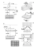
Make an air evacuation hole in the wall (diameter 133 mm) as shown in Fig. 1 which gives all the measurements required
for the various possible installations.
2) The hood is fitted with two air outlets, one at the top (Fig. 2B) and one at the rear (Fig. 2A), which can
be used according to requirements. In the ducting version, mount the flange (C) on the opening used and close
the other opening with the plug (E). In the filtering version, close both openings with the two plugs (E).
3) Wall mounting : Drill 4 holes in the wall using the measurements shown in Fig. 3 and insert the screw anchors;
take 2 of the supplied screws (Fig. 4G) and screw them into the uppermost anchors without tightening them. Attach
the hood to the 2 screws and, working from inside, fully tighten them. Complete mounting by inserting and tightening
the other 2 screws H (Fig. 4).
4) Mounting under a wall unit : If the ducting version of the hood is mounted with the air outlet in the upper opening
(Fig. 2B), before mounting, drill a 133 mm diameter hole in the wall unit (Fig. 5).
Drill 4 holes in the wall unit using the measurements shown in Fig. 6. Attach the hood with 4 screws working from inside
the wall unit (the 4 screws are not supplied).
5) For the ducting version: connect a flex tube to the hood flange using a metal retainer clamp. The tube and clamp
are not included in the supply.
6) Make the electrical connection.
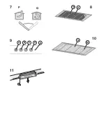
7) CHECK THAT THE DUCTING-FILTERING LEVER IS IN THE RIGHT POSITION: The lever is found on the motor
unit and must be positioned on the symbol (
P
) in the case of installation in ducting version, on the symbol (
Q
) in
the case of installation in filtering version (Fig. 7).
8) CHARCOAL FILTER/S (A) - Fig. 8: one or more charcoal filters are required in the filtering version. If they are not
yet installed in the hood, fit them inside the grease filter/grille (M). Charcoal filters are not required In the ducting version.
If they are already installed in the hood remove them together with the relative filter retainers.


