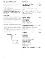
Mounting the upper chimney panelling
–
Push the upper chimney panelling
over the inner frame and screw
on with 2 screws. If you are using
an external motor, ensure that the
control line of this motor is guided
through the inner frame down to
the switch and control unit. The
shelves of the inner frame have
recesses for the cable.
Alternative installation sequence
If you find that the upper chimney panel cannot be pushed from below over
the inner frame, proceed in a slightly different way:
–
Push the upper chimney panel from above over the lower inner frame.
–
Insert the upper inner frame onto the lower inner frame and secure tight.
It is best to measure the necessary height.
–
Screw the inner frame to the ceiling.
–
Push the upper chimney panel upwards and screw to the inner frame.
Mounting the lower chimney panel
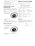
If necessary, you have to create space under the hood so that you can
push the bottom chimney panel over the inner frame.
–
Push chimney panel over the inner frame; align the opening for the con-
trol panel to face forwards.
–
If you do not want to hold the pa-
nel the entire time, you can secu-
re it to the inner frame at the bot-
tom with a screwdriver.
Insert vent
–
Recirculating operation: Insert the
vent in the opening in the lower
flue, clipping it firmly to the de-
flector.
–
Venting operation: Insert the vent
as a decorative plate in the open-
ing in the lower flue.
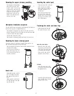
Inserting the control part.
–
If necessary, unpack the control part.
–
Guide the control part hanging
down from the hood from the insi-
de through the opening in the
chimney panel.
–
Then insert the control part from
the outside into the opening the
right way round. Press in carefully
until you can see that the control
part is sitting properly.
Fastening the motor and fume trap
–
Fasten the glass fume trap with
four screws to the inner frame.
Hood with external motor:
–
Remove the cover of the switch
and control unit and connect the
control line of the external motor
to the terminal strip illustrated.
–
Then screw the cover onto the
switch and control unit again.
All hoods:
–
Connect the power supply cable
to the switch and control unit with
the appropriate cable.
–
Secure the switch and control unit
above the middle strip in the hood
opening with two screws.
IKD 954.1
21


