


To avoid possible risks of fire always comply with the indicated instructions when cleaning anti-grease filters and
when removing grease deposits from the appliance.
MAINTENANCE
Thorough servicing guarantees correct and long-lasting operation.
Any fat deposits should be removed from the appliance periodically depending on amount of use (at least every 2
months). Avoid using abrasive or corrosive products. To clean painted appliances on the outside, use a cloth dipped
in lukewarm water and neutral detergent. To clean steel, copper or brass appliances on the outside, it is always best
to use specific products, following the instructions on the products themselves. To clean the inside of the appliance,
use a cloth (or brush) dipped in denatured ethyl alcohol.
DESCRIPTION
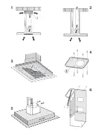
The unit can be found in filtering hoods or ducting hoods.
In the
Filtering version
the air and the kitchen fumes that are conveyed by the apparatus are depurated by the
charcoal filter and put back into the room through the small grilles of the ventilation flue (Fig. 1). ATTENTION:
When using the filtering version, a charcoal filter and an air baffle (Fig. 1A) must be used, which placed at the
top of the structure, allows the air to recycle back into the room.
In the
Ducting version
, cooking vapours and odours are conveyed straight outside by a disposal duct which passes
through the ceiling (Fig. 2).
INSTALLATION
ATTENTION: Three people are required for proper installation; the unit should be installed by a qualified operator.
Also follow carefully each step of the assembly instructions, and once installation has been completed, make sure
that the hood is firmly secured in place.
1. To facilitate installation, before starting remove the
grease filter
: press inward on the clamp at the handle and pull
the filter downward (Fig. 3).
2. For assembling it is essential to: – Prepare the connection to the mains within the telescopic flue. – If your unit is
installed in a ducting hood, prepare the air exhaust hole.
3. When installing ducting hoods, to achieve the best possible conditions use an
air exhaust pipe
that : is as short as
possible, has a minimum of curves (maximum angle: 90°), is made of a material that complies with the standards (which
vary from nation to nation) and is smooth on the inside. It is also advisable to avoid any drastic changes in pipe section
(diameter: 150 mm).
4.
ASSEMBLING -
Using the special drilling template, drill the holes for fixing to the ceiling on the vertical side of your
hob. Carefully observe all the indications for final positioning of the apparatus. Take into account that one of the template
axes must correspond to the axis of the hood controls. Fix the bracket to the ceiling using the screws and screw anchors
provided (Fig. 4). Be careful, because the position of the bracket determines the final position of the apparatus: the side
with the slot B corresponds to the side opposite the controls. Assemble the plate of the electrical system fixing it with
2 screws and 2 metal washers (Fig. 5).
Ducting version: Fix the telescopic structure to the bracket by means of 4 screws (provided), running the air evacuation
pipe through the telescopic structure and the electric power cable through the special hole in the bracket (Fig. 6). Adjust
the height of the telescopic structure by means of the four retaining screws C (Fig. 7), taking into account that the height
of the hood is 88 mm and that the distance between the hood and the hob must be at least 650 mm (Fig. 8). Take the
upper flue (with the round slots) and fit it on the telescopic structure with the slots facing upwards; fit the flue to the bracket
with 2 screws (Fig. 9). Take the lower flue and fit it in the same manner as before; slide it to the top and stop it in that
position using a adhesive tape (Fig. 10).
Take the flange with the metal valve (Fig. 11H) and assemble it onto the opening of the hood for air venting, pressing slightly.
Fit the hood to the telescopic structure by means of 4 screws (provided) – Fig. 12.
Through openings D (Fig. 12) fix the air evacuation pipe to flange H.
Make the electrical connection by means of the power cable. Remove the adhesive tape and pull the lower flue downwards,
placing it gently onto the apparatus. Installation is now complete and the grease filters can be reassembled.
Filtering version: Fix the telescopic structure to the bracket by means of 4 screws (provided), running the electric power
cable through the special hole in the bracket (Fig. 6). Adjust the height of the telescopic structure by means of the four
retaining screws C (Fig. 7), taking into account that the height of the hood is 88 mm and that the distance between the
hood and the hob must be at least 650 mm (Fig. 8). Insert the air baffle (F) in the structure (Fig.13). Through the openings
E (Fig.14), fit the flange (G) to the baffle (F) locking it with a turning movement. Fix a flexible pipe to the flange (G) for
air evacuation (Fig. 14). Take the upper flue (with the round slots) and fit it on the telescopic structure with the slots facing
upwards; fit the flue to the bracket with 2 screws (Fig. 9). Take the lower flue and fit it in the same manner as before;
slide it to the top and stop it in that position using a adhesive tape (Fig. 10).
Take the reduction (Fig. 15L) and assemble it onto the air venting opening of the hood, pressing slightly.
Fit the hood to the telescopic structure by means of 4 screws (provided) – Fig. 16.
Fix the air evacuation pipe onto the reduction (L). Make the electrical connection by means of the power cable. Remove
the adhesive tape and pull the lower flue downwards, placing it gently onto the apparatus.
Install the charcoal filter clipping the 2 filter clips into place (Fig.17) and turn the filter upwards.
Summary of Contents for IKD6700.0
Page 6: ...1 2 3 4 5 6 ...
Page 7: ...7 8 9 10 11 ...
Page 8: ...12 13 14 15 16 ...
Page 9: ...17 18 19 ...


