
10
GB
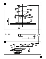
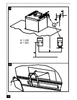
1) Draw a vertical line up the wall from the centre of the cooking appliance below as illustrated in
fig. 1 - item 1.
2) Draw a horizontal line through the vertical at 650 + item A when fitting above an electric hotplate or
at 700 + item A when fitting above a gas hotplate as illustrated in fig. 1.
3) Mark the hole centres for the canopy fixing brackets item 4 at item B mm as illustrated in fig. 3.
4) Draw a horizontal line through the vertical 40 mm from the ceiling or from the point where the chim-
ney will terminate.
5) Mark the hole centres for the upper chimney fixing bracket (item 2) at item C (fig. 1).
6) Drill the holes for the three fixing brackets using an 8 mm masonry bit.
7) Fix the brackets item 4 for canopy using the 5 x 50 mm hexagonal screws and rawl plugs supplied.
8) Fix the chimney support bracket (item 2) using the No 5 x 50mm hexagonal headed screws and rawl
plugs supplied.
9) Hook the canopy item 5 onto the wall brackets item 4 as illustrated in fig. 3.
10) To ensure the cooker hood is aligned correctly adjust the screws on the top of the canopy as illus-
trated in fig. 3.
11) When the hood is aligned correctly mark the hole centre on the wall for the security fixing screw item
8, which is located in the right hand bracket on the top of the canopy.
12) Unhook the canopy from the wall and drill the hole for the security fixing screw.
13) Hook the canopy onto the wall and fix the No 5 x 50mm headed screw and rawl plug to secure the
canopy to the wall.
14) Connect the ducting to the spigot item 6.
15) Place the telescopic chimney item 7 onto the canopy and extend the upper chimney section around
the chimney support bracket item 2 and fix the chimney to the bracket using the two No 4 x 8mm self
tapping screws.
•
RECYCLING
The hood is easily converted to the recycling mode by installing the recycling ducting adapter item A, a
short length of 150mm ducting and a charcoal filter (optional).
1) Fix the recycling ducting adapter to the chimney support bracket item 2 as illustrated in fig. 2 while
connecting a cut length of 150mm round ducting between the recycling ducting adaptor and the
ducting spigot item 6 on top of the canopy item 5.
2) Remove the metal grease filters and insert the charcoal filter into the base of the motor housing and
secure the filter with two metal securing straps item A as illustrated in fig. 4.
4
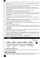
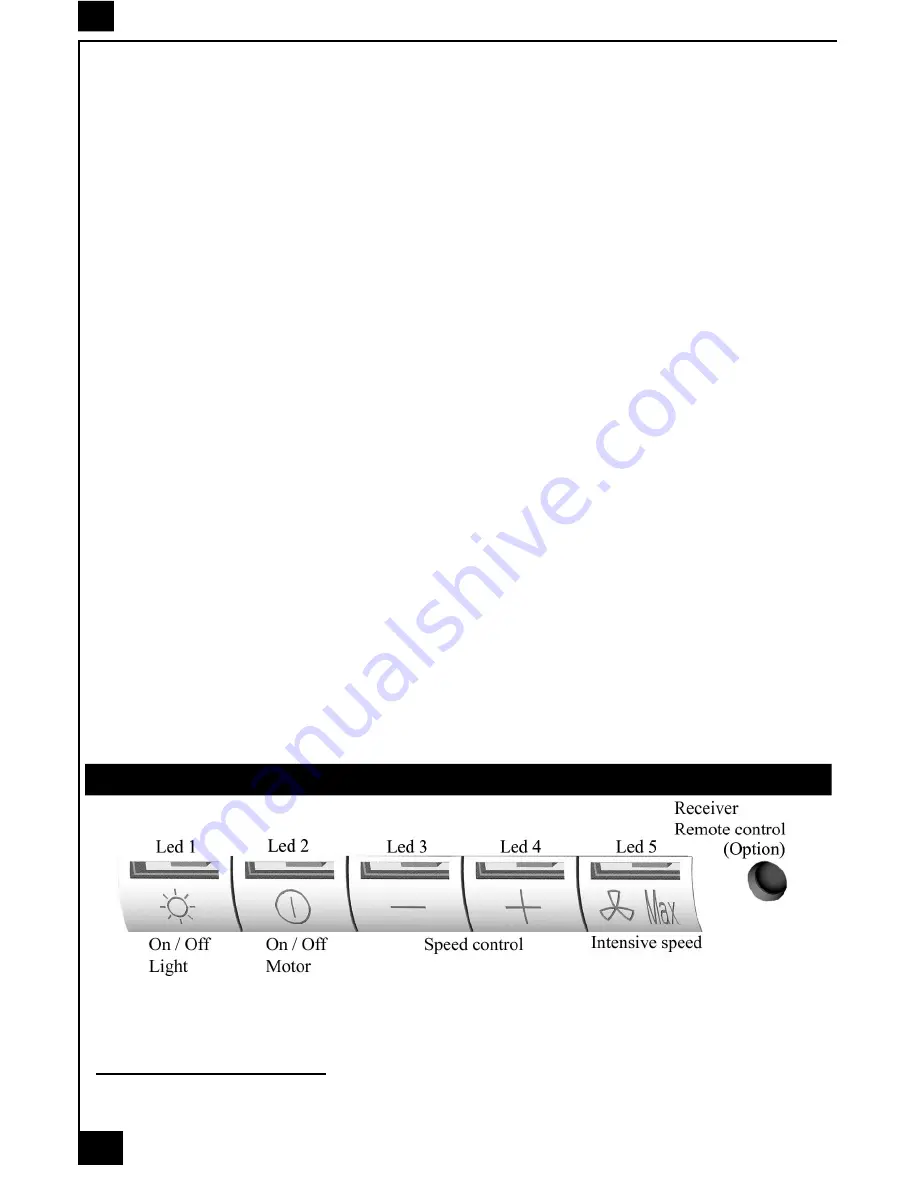
OPERATION
A - EXTRACTION OR RECYCLING
Your cooker hood is supplied in the extraction mode. To use the cooker hood in the recycling mode re-
programme the hood as follows:
Starting in the recycling mode
Press the ‘+’ button for 20 seconds (while the motor and lights are switched ‘OFF’) and the five LED
lights will flash twice to indicate confirmation that the cooker hood is in the recycling mode.
Summary of Contents for KD 12450
Page 1: ......
Page 9: ...31 2 2 1 C 240 ...
Page 10: ...32 3 4 4 A 290 B 250 A ...
Page 11: ...33 ...


