21
Part 1 - INSTALLATION INSTRUCTIONS
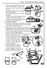
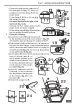
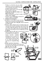
- Remove the plug from the upper part of
the ducting fan unit (
fig. 17
), as it is not
possible to insert the flange
F
with the
plug in place.
- Fit the flange
F
Ø120 or 150 mm (
fig.
18
), replace the plug.
· Air outlet directed to the right or left
hand side (fig. 4a-b).
- Remove the four screws fastening the
plastic frame, as shown in
fig. 16
.
- Fit the ducting spigot
R
(
fig. 19
) and replace
the four screws removed as above.
3 - Fixing the chimney
a) Loosen the screws
M
fixing the two parts
of the chimney and pull the inner section
I
(
fig. 20
)
almost all the way out. Remove the protective film
P
.
b) Rest the lower section of the chimney in its housing on
the top of the hood canopy. Lower the ducting fan unit
until it reaches the wall bracket
S
and fix it using the
screw
H
provided (
fig. 21
). Fit the cover
D
(provided)
on the wall bracket
S
(
fig. 22
).
c) Insert gasket
G1
(found in the accessory bag) on the
base of chimney stack
A
, so
that it adheres perfectly to the
shape of chimney stack
A
. Then
fix chimney stack
A
to the hood
unit
C
using four of the screws
provided
E
(
fig. 23
).
d) Insert the transparent seal
Q
(provided), so as to eliminate
any play between the two parts
of the chimney (
fig. 24
). Lock
the screws
M
.
e) Remove the support rod
B
.
1 7
1 7
1 8
1 8
2 0
2 0
1 9
1 9
E
E
E
E
A08_TL
A
G1
C
2 1
2 1
2 2
2 2
2 3
2 3
2 4
2 4
Summary of Contents for KD 674.1 GE
Page 2: ......
Page 68: ...4329309 07 000727 ...

