18
MAINTENANCE SCHEDULE
3. Place a 3.25” thick spacer in the front station, and start closing the vise
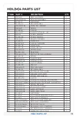
and this will drive the holding block (#27 in Fig. 11) out of the vise body.
4. Once the holding block is clear of the body, reverse the screw rotation,
so the spacer can be removed.
5. Remove the stationary and front movable jaws from the vise.
6. Remove the chip guards
7. The nut and screw assembly can now be slid out freely from the vise.
8. Thoroughly clean and oil the nut and screw assembly, vise body, and
jaws so there are no chips or debris left.
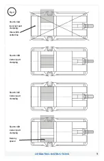
9. Now it’s time to reset the timing. Turn the rear nut counter clockwise
until you can feel resistance. Turn the nut back the other way until the
front and rear front are in line with one another. This sets the timing of
the front and rear nut. (See Fig. 12 below)
10. Slide the nut and screw assembly, rear nut first, into the vise body up
to the holding block. See Fig. 11 for holding block identification.
11. Install stationary and rear movable jaws. Place a 3.25 spacer in the
rear station and start closing (clockwise rotation) the vise. You may
have to help get the friction clamp (rectangle piece with tapered ends)
started into the body by using a pair of pliers to help compress the
spring material.
12. Once the holding block is inside the body, reinstall the M10 button
head cap screw in the end of the body. Install front movable jaw.
13. Your vise is now ready to use.
MAINTENANCE SCHEDULE
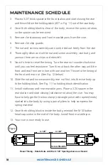
Fig.12
4.125"
4.125"
Screw Shoulder
Reset Timing - Rotate Nuts until the 4.125" Spacing above is achieved

