5
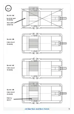
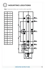
1. Position vise on your machine table, pallet or tombstone using the
.625 or 16 MM (.6299”) locating holes found on the bottom of the vise.
We recommend using the holes that are the farthest apart for better
accuracy.
2. Bolt in place using strap clamps placed on the clamping ledge as
indicated by “Clamp Here” sticker or by bolting directly through the
vise body. When bolting through the body, the stationary jaw must be
removed to gain access to those holes. The outboard holes have plugs
to keep debris out and must be removed if you wish to use those holes
as well. Replace plugs after bolts are secured.
VISE INSTALLATION INSTRUCTIONS
INSTALLATION INSTRUCTIONS
Do not attempt to lift the vise by attaching to any of
the jaws or injury may result. Always attach lifting
device to the vise base frame.
!
CAUTION
NOTE:
Some of the clamp holes are at inch locations and some are at
metric. For exact hole locations, go to pages 13-14 in this manual.
3. After the vise is mounted in place, add the vise jaws to the base
assembly. See jaw installation instructions that came with the jaw
kit. If a hard jaw kit “J style” was installed, tram the stationary jaw for
straightness prior to using. If it exceeds .0006” in six inches, remove
stationary jaw and disassemble the 10mm bolt, the tapered top clamp
and .750 dia. split sleeve and clean with solvent and a clean cloth. Do
Not apply grease or oil to these components. Re-assemble and retest.
This should not be necessary when using the carvable type unless a
high degree of accuracy is required and you are not recutting the jaw
contour.


