40
3BA00226 • 2016-11-16 • Rev. 2
Ersa HR 200
TOP HEAT
Smooth
Intensive
Power
level
1
2
3
4
Time*
>180 s
180 - 120 s 120 - 90 s
90 - 60 s
1
Ultra light
weight
Sensitive bottom
side
Intensive
top
2
Sensitive
top side
Typical SMT
application
3
4
Intensive bottom
HEAVY
DUTY
CAUTION
*expectable soldering time, depending on application
and preheating with bottom heater
B
O
TT
O
M
H
EA
T
In
te
ns
iv
e
Sm
oo
th
PA
R
A
M
ET
ER
S
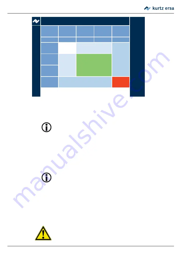
Parameter diagram: recommended heat output for PCB types during soldering
and desol-
dering. This diagram is attached as a chart to the housing of the HR 200 and can also be
called up on the Internet at www.kurtzersa.com.
The heating plate IRHP100A is in standby mode at 30% output and
switches to the set output level when the foot switch is pressed.
■
By pressing the foot switch, the heating process of the top heater and – if enabled –
of the bottom one is started.
■
When the solder is molten, remove the component with an appropriate tools and
release the foot switch. If necessary, switch off the bottom heater using control knob
⑪
or the mains switch of the heating plate.
We recommend using fume extraction system (e.g. Ersa EASY ARM 1).
6.3.3
Soldering
■
Position the PCB in the PCB holder at a distance of about 30 mm below the top heater.
■
Prepare the soldering point on the PCB with flux and/or solder paste. Then place the
component.
CAUTION! Hazard of material damage!
Also adjacent areas are heated and must, therefore, be protected against
heat if necessary.
Function description


