7 | Tutorial – Soldering or desoldering a component
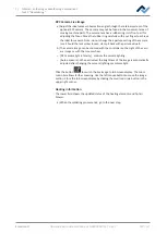
Replacing the soldering nozzle
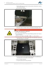
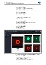
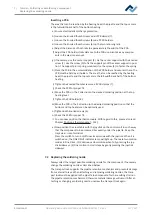
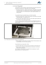
Inserting a PCB
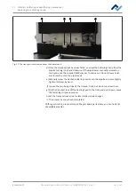
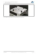
The area that can be reached by the heating head, the pipette and the top camera
is the full-width back half of the bottom heating.
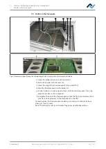
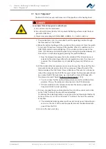
a) Ensure electrostatic discharge protection.
b) Loosen the knurled thumb screws on all PCB clamps (7).
c) Loosen the knurled thumb screws (8) on all PCB holders.
d) Loosen the knurled thumb screws (6) on the two retaining rails.
e) Adjust the distance of both rails to approximately the width of the PCB.
f) Adjust the PCB holders/rails distance to the PCB size. Also take any compon-
ents in the way into account.
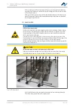
g) If necessary, use the center support (2). Fix the center support with the knurled
screw (1). Use the screw (5) to fix the support pin of the center support in posi-
tion. The support pin is spring-mounted. Use the screw (3) to fasten the spring.
h) Place the PCB in the accommodation of the PCB holder and secure it there. The
PCB must be held by all holders. The area that can be reached by the heating
head, the pipette and the top camera is the full-width back half of the bottom
heating.
i) Tighten the knurled thumb screws on all PCB clamps (7).
j) Check the PCB for proper fit.
k) Move the PCBs in the Y direction to the desired soldering position at the top
heating level.
l) Tighten the PCB holder (8).
m)Move the PCB in the X direction to the desired soldering position so that the
bottom and top heaters can be optimally used.
n) Tighten both knurled screws (6).
o) Check the PCB for proper fit.
ð
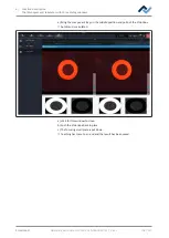
You can now position the thermocouple. With regard to this, please also read
Chapter Position a thermocouple [
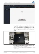
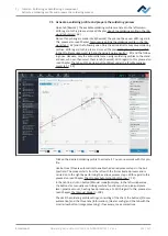
a) Now position the cross table with the joystick on the control unit in such a way
that the component to be processed lies exactly under the pipette. Keep the
track clear, risk of collision!
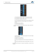
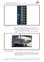
Press the switch to turn on/off slow travel mode with the joystick. When it is
switched on, the FINE DRIVE indicator lamp will light up. There are two motion
modes in Fine Drive: (1) Continuous slow motion when fully pressing the joy-
stick sideways. (2) Fine motion in small steps by gently pressing the joystick
sideways.
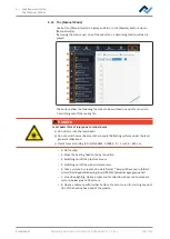
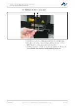
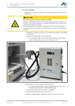
7.2 Replacing the soldering nozzle
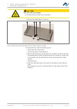
Always select the largest possible soldering nozzle for the component. If necessary,
change the soldering nozzle as described below:
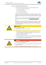
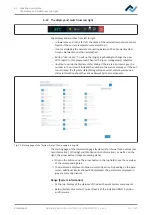
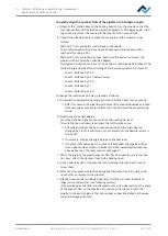
The transport lock supports the pipette retention mechanism and prevents damage
from external forces. When attaching and removing soldering nozzles, the trans-
port lock must be applied to the pipette to compensate for the resulting strain on
the pipette retention mechanism. Otherwise material damage will occur! After at-
taching or changing a soldering nozzle, unscrew the transport lock again.
Ersa GmbH
Operating instructions HR 550 XL EN 3BA00247-01 | Rev. 1
117 / 157

