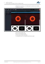
7 | Tutorial – Soldering or desoldering a component
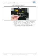
Replacing the soldering nozzle
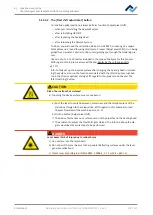
CAUTION
Risk of burns from hot surfaces!
a) Touching the device surfaces may cause burns!
a) Wait for the heating head to cool down.
6
5
2
4
4
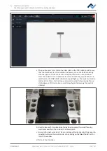
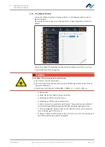
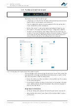
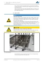
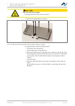
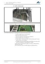
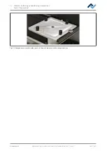
Fig. 24:
The transport lock in the removed state. The plastic part (5) is not required.
The transport lock consists of the following parts:
– (2) Handle of the transport lock
– (4) Two fixing strips, each bolted twice
a) (5) Plastic clamping piece, screwed twice. Not needed for nozzle change. Store
the clamping piece and any associated screws so as to be able to screw it back
to the transport lock should the Rework system be subsequently carried or
shipped.
– (6) Pipette recess
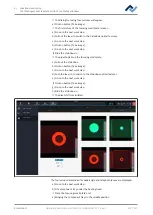
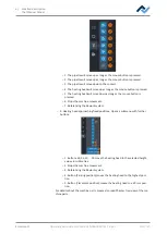
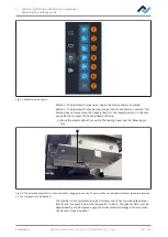
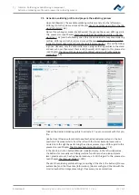
a) Use button [Manual mode] in tab Rework to call up button column Manual
mode .
By moving the mouse over one of these buttons, a describing tool tip will be
displayed.
Ersa GmbH
Operating instructions HR 550 XL EN 3BA00247-01 | Rev. 1
118 / 157

