5 | Commissioning
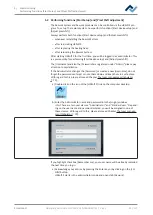
Performing functions [Start Setup] and [Pixel Shift adjustment]
Rework
Archive
User administration
Profile management
Administration
Manual Mode
Desoldering
Name
Placement
Profile settings
Search
Heater config
Information
Board
Component
Control sensor
Adaptor (head)
Dip mode
Placement mode
Drop height
TC1
Distance 50 mm
No automation
Placement
Heating head position
Placement
Time
Soldering
Inspection
Soldering
Desoldering
Synchronize
Process automation
Combined
Nozzle
START/REFERENCE
Pickup mode
Component tray
Desoldering
Inspection
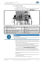
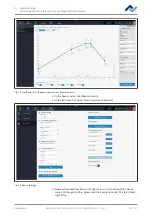
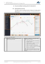
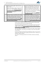
Fig. 15:
Tab [Rework ] in the administrator view. Example picture.
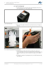
b) In the header, select tab [Administration].
c) In the left menu bar, select menu item [Device options].
Style
Device selection
Selected device
Rework
Archive
User administration
Profile management
Administration
HRSoft 2 options
Graph options
Device options
Force sensor parameters
Firmware update
System board update file
Power board update file
Satellites update file
Device setup
Optional tools
Pixel shift
Move to transport position
Adjust pixel shift
Firmware update
Start device setup
Select file
Select file
Select file
Temp. offset (120° C)
Channel TC 1
Reduce Z-axis velocity
Distance to reduce z-axis velocity
Force sensor tolerance
Force sensor safety
Force sensor contact level
Force sensor contact level pcb
Send
Channel TC 2
Channel TC 3
Device transport position
Select file
Select file
Xmos update file:
Amtel update file:
Scavenger active
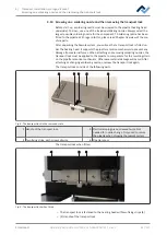
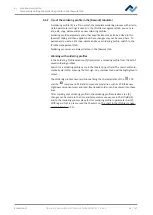
Fig. 16:
Device settings
d) Now perform both functions in the right column. First perform [Start device
setup]. With regard to this, please read the description under The [Start teach-
ing] button.
Ersa GmbH
Operating instructions HR 550 XL EN 3BA00247-01 | Rev. 1
53 / 157

