6 | Function description
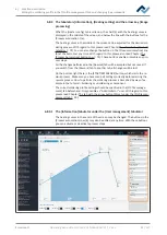
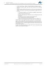
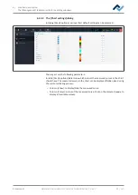
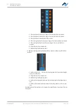
The [Management] tabulator with three dialog windows
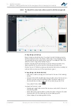
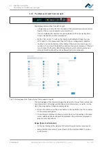
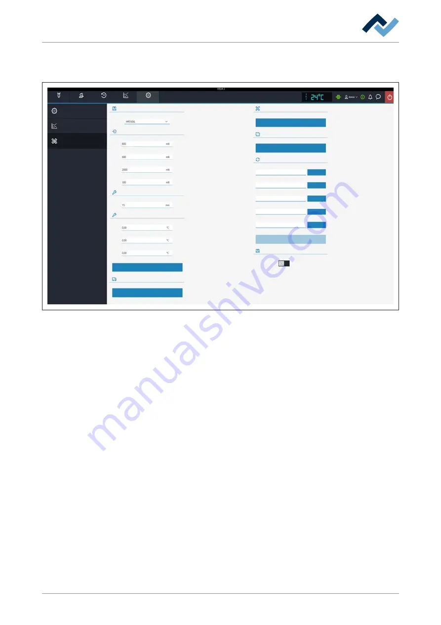
6.12.3 The [device settings] dialog
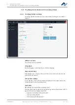
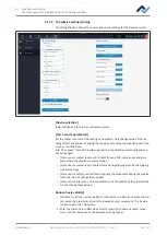
Use dialog [Device options] to access various pre-settings for the Rework system.
Style
Device selection
Selected device
Rework
Archive
User administration
Profile management
Administration
HRSoft 2 options
Graph options
Device options
Force sensor parameters
Firmware update
System board update file
Power board update file
Satellites update file
Device setup
Optional tools
Pixel shift
Move to transport position
Adjust pixel shift
Firmware update
Start device setup
Select file
Select file
Select file
Temp. offset (120° C)
Channel TC 1
Reduce Z-axis velocity
Distance to reduce z-axis velocity
Force sensor tolerance
Force sensor safety
Force sensor contact level
Force sensor contact level pcb
Send
Channel TC 2
Channel TC 3
Device transport position
Select file
Select file
Xmos update file:
Amtel update file:
Scavenger active
[Device selection]
[Selected device]: to select your Rework system.
[Force sensor parameters]
Set the contact sensors of the placing head pipette. Only change values if the res-
ulting effects are known. Changing these values may cause the pipette to exert too
much or too little force.
Info: The contact force of the soldering nozzle is controlled automatically and can-
not be changed.
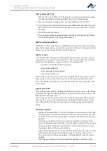
– [Force sensor contact level pcb]: contact force on PCB, component and glass
plate where the pipette movement stops.
– [Force sensor contact level]: contact force during dipping at which the dipping
movement stops.
– [Force sensor safety]: contact force stopping the movement during the pipette
fast drive. Do not change these values!
– [Force sensor tolerance ]: Force specification of the hysteresis for pipette drive.
Do not change these values!
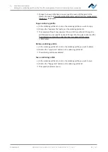
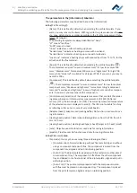
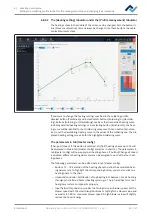
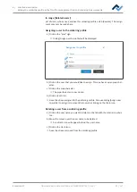
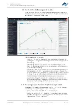
Reduce Z-axis velocity]
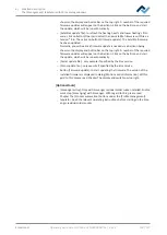
– [Distance to reduce z-axis velocity]: For the last few millimetres before the con-
tact point, the pipette must switch to slowed contact movement. The 0 value
corresponds to the PCB surface.
a) Enter the distance in millimetres at which to switch to slowed contact move-
ment. For tall components, the distance must be higher.
Ersa GmbH
Operating instructions HR 550 XL EN 3BA00247-01 | Rev. 1
98 / 157

