6 | Function description
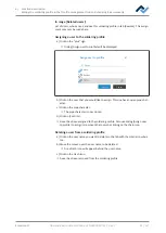
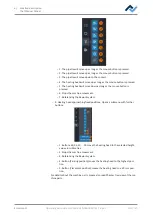
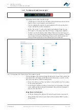
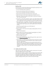
The [Management] tabulator with three dialog windows
6.12.3.2 The [Pixel shift adjustment] button
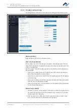
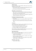
To redefine optical positions, always perform function [Adjust pixel shift]:
– whenever reinstalling the Rework System
– after reinstalling HRSoft 2
– after replacing the heating head
– after relocating the Rework System.
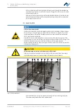
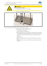
To do so, you will need the calibration kit item no. 324627, consisting of a square
black plate and a round focusing small plate. Process [Adjust pixel shift] is run being
guided by an assistant, similar to the wizard guiding you through the soldering pro-
cess.
Use one of size 5 or 10 nozzles included in the scope of delivery for this process.
With regard to this, please also read Chapter Replacing the soldering nozzle
[
Info: To fully set up the Rework system after changing the heating head or relocat-
ing the system, also run the function associated with the [Start device setup] but-
ton in the [Device options] dialog. With regard to this, please read Chapter The
[Start teaching] button.
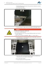
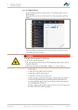
CAUTION
Risk of burns from hot surfaces!
a) Touching the device surfaces may cause burns!
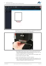
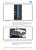
a) Push the lever to switch between normal view and the telephoto lens of the
Visionbox through to the teleposition. With regard to this, please also read
Chapter Overview of the machine parts, no. 11.
b) Click on button [Adjust pixel shift].
ð
The device first carries out a reference run of the pipette and the heating head.
ð
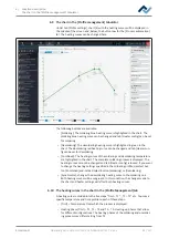
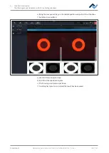
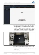
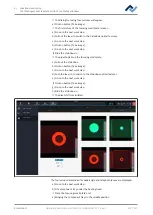
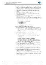
The assistant to adjust the Pixel Shift gets started. The info line above the dia-
gram describes the work steps to be performed.
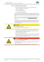
DANGER
Laser beam! Risk of injury due to retinal burns
a) Do not stare into the laser beam!
b) Do not point the laser beam at other people! Reflecting surfaces under the laser
generate reflections!
c) Class 2 laser according to DIN EN 60825-1:2008-5, P < 1 mW, λ = 650 nm
Ersa GmbH
Operating instructions HR 550 XL EN 3BA00247-01 | Rev. 1
105 / 157

