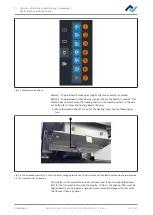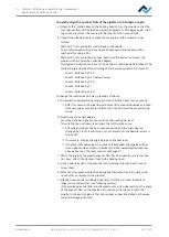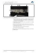
7 | Tutorial – Soldering or desoldering a component
Insert the PCB
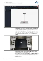
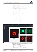
In this tutorial you will find an example of how to work through the desoldering
and soldering processes as well as step by step through the entire rework process
in the software wizard.
With regard to this, please also read the detailed descriptions of the tabs, menus
and commands used here and the associated warning notices that are provided
from Chapter Read this first!.
7.1 Insert the PCB
NOTE
ESD sensitive components!
Electronic components may be damaged by electrostatic discharges. Please observe
the warnings on the packaging or contact the manufacturer or supplier. To protect
these components, the system should be placed in an electrostatic protected area
(ESD = electrostatic discharge).
The HR 550 can be easily integrated in environments of this kind. Using one of the
front buttons, the user can connect for example an ESD wristband. The housing of the
HR 550 is connect via power cord to the earth wire of the supply network.
When handling the device, observe all general safety measures normally required for
ESD sensitive components.
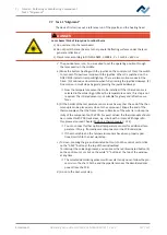
CAUTION
Material damage caused by overtightening the PCB holder!
Tighten all screws just enough to ensure that the PCB is securely fixed. Excessively
high tightening torques can cause damage to threads and circuit boards!
3
4
1
7
9
2
8
5
6
9
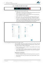
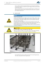
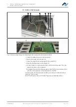
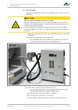
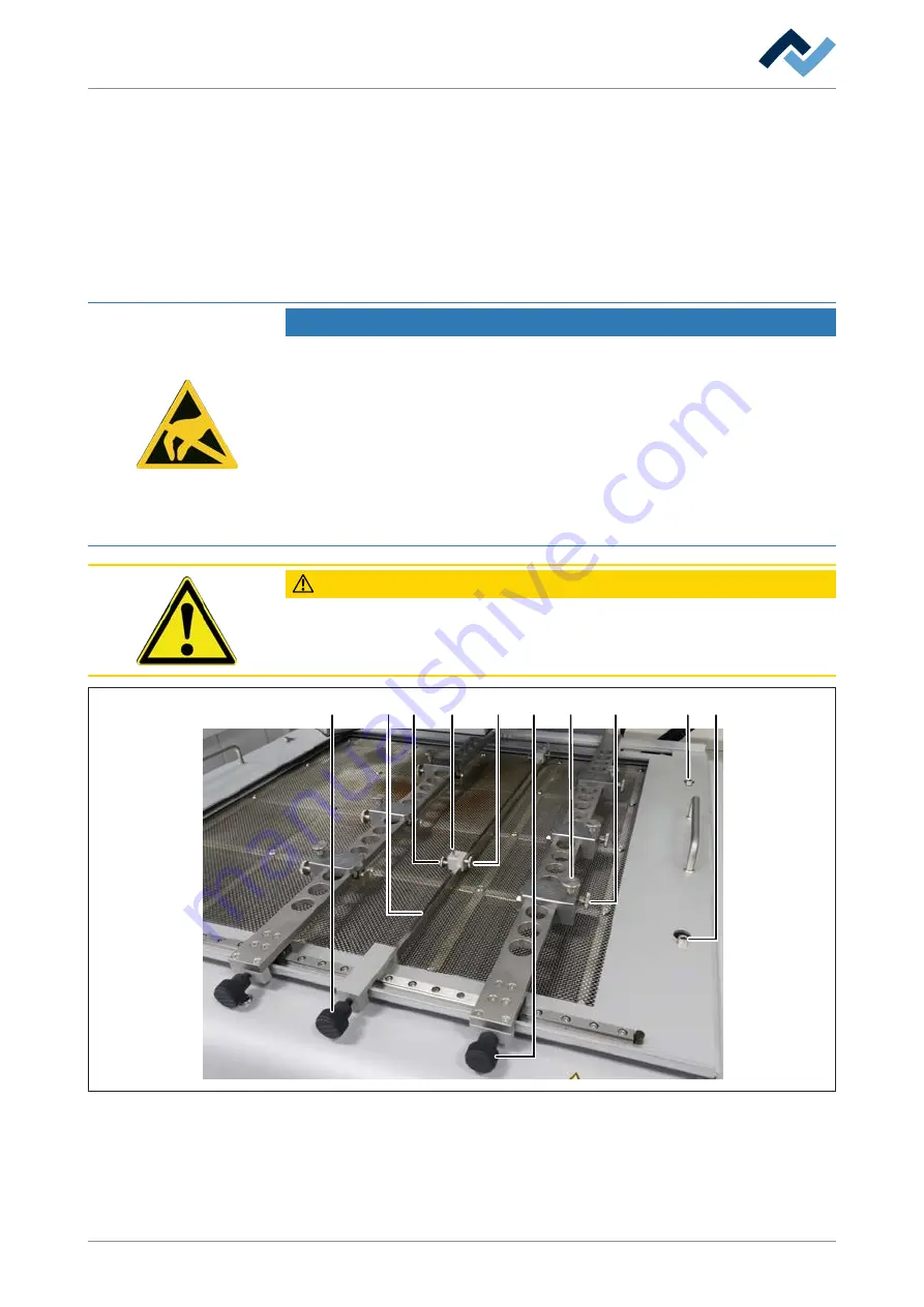
Fig. 23:
PCB frame details
Info: The PCB frame can be removed by loosening the four retaining screws (9).
This allows using several frames for replacement.
Ersa GmbH
Operating instructions HR 550 XL EN 3BA00247-01 | Rev. 1
116 / 157

