7 | Tutorial – Soldering or desoldering a component
Task 1 “Alignment”
7.7 Task 1 “Alignment”
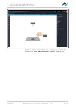
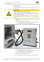
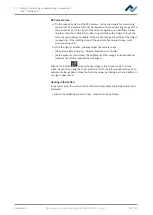
The device first carries out a reference run of the pipette and the heating head.
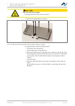
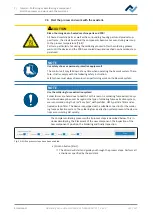
DANGER
Laser beam! Risk of injury due to retinal burns
a) Do not stare into the laser beam!
b) Do not point the laser beam at other people! Reflecting surfaces under the laser
generate reflections!
c) Class 2 laser according to DIN EN 60825-1:2008-5, P < 1 mW, λ = 650 nm
ü
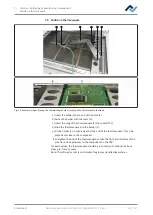
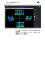
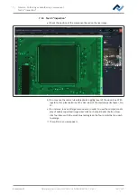
The position laser is on. You are asked to set the operating position through
the laser exactly in the middle.
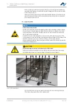
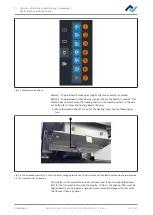
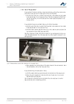
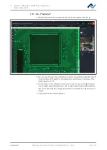
a) Move the bottom heating with the joystick on the control unit. Press the switch
to turn on/off slow travel mode with the joystick. When it is switched on, the
FINE DRIVE indicator lamp will light up. There are two motion modes in Fine
Drive: (1) Continuous slow motion when fully pressing the joystick sideways. (2)
Fine motion in small steps by gently pressing the joystick sideways.
ð
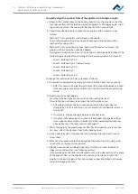
Now the temperature sensor has to be installed. If the infrared sensor is
selected in the soldering profile as the temperature sensor, this step is not
required. The infrared sensor is not suitable for glossy and reflective sur-
faces.
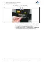
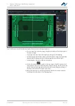
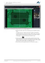
b) Fit the holder of the temperature sensor in such a way that the end of the ther-
mocouple can be placed very close to the component. Shape the end of the
thermocouple so that the frontal three millimetres of the wire lie in close prox-
imity of the component on the PCB. For exact values, the thermocouple should
be in contact with PCB track areas, e.g. circuit path or mass. With regard to
this, please also read Chapter Position a thermocouple [
ð
You can connect further optional temperature sensors for additional tem-
perature info, e.g. from adjacent components or the PCB underside.
ð
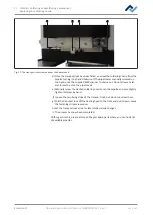
If the cross table and the temperature sensor have been properly posi-
tioned, switch to the next work step.
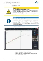
c) To do so, pressing the green illuminated button (>) on the control unit or click
on the “0529” button at the top of the window.Next
To interrupt the soldering process, you can press the red illuminated button (X)
on the control unit, or click on the white “X” button at the top of the window,
at any time.
ð
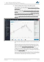
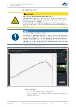
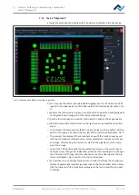
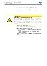
The selected desoldering process will now start and you can follow the pro-
cess run in the chart. At the end the pipette removes the desoldered com-
ponent from the PCB.
d) Go on to the next work step.
Ersa GmbH
Operating instructions HR 550 XL EN 3BA00247-01 | Rev. 1
127 / 157

