7 | Tutorial – Soldering or desoldering a component
Task 4 "Preparation"
7.10 Task 4 "Preparation"
If you selected the dip mode [No automation] (soldering without flux material dip
and without component with solder paste in the print template):
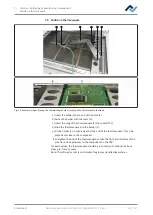
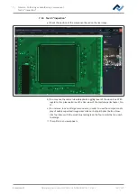
a) With the aid of the laser, position the component to be soldered in the middle
and properly align it on a component tray. Then the component is lifted from
the component tray. Then the component must be aligned and placed in sol-
dering position.
If you selected the dip mode [Auto. Dip], e.g. for QFN components:
a) With the aid of the laser, position the component to be soldered in the middle
and properly align it on a component tray.
b) With the doctor blade apply flux material gel in the dip template and place the
dip template into the other component tray.
Then the component is taken from the component tray and dipped in the flux ma-
terial of the dip template. Then the component must be aligned and placed in sol-
dering position.
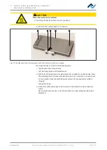
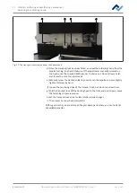
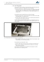
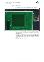
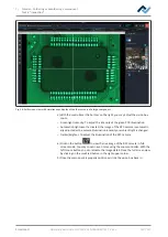
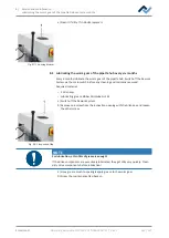
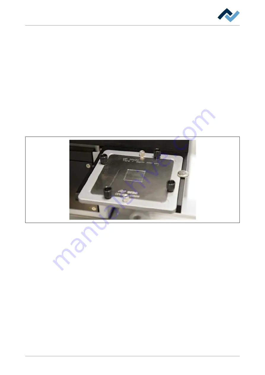
Fig. 31:
Dip template covered in flux material on the component tray
a) After applying flux material gel with the doctor blade in the dip template, place
the dip template in the other component tray.
If you selected the print mode [Auto. Print]:
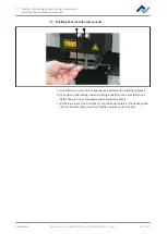
a) With the doctor blade, apply solder paste on the bottom of the component.
b) Place the print template in a component tray and make sure it is correctly
aligned with the component.
The component is lifted by the print template. Then the component must be
aligned and placed in unsoldering position.
Ersa GmbH
Operating instructions HR 550 XL EN 3BA00247-01 | Rev. 1
131 / 157

