7 | Tutorial – Soldering or desoldering a component
Task 5 “Alignment”
7.11 Task 5 “Alignment”
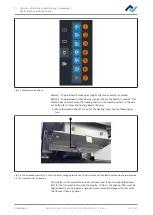
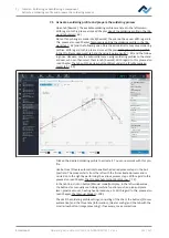
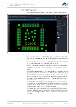
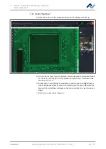
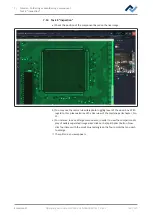
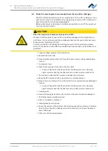
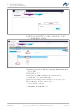
a) Align the component perfectly with the board as indicated in the live image.
Alignment
Desoldering
Alignment
Release
Inspection
Provide
Inspection
Soldering
Complete
Parameters
Red light intensity
Component scaling
Green light intensity
Red and green overlap information
Contrast component
Contrast board
Split optics
Next
Back
Bigger
Smaller
Fig. 33:
Component before correcting its position
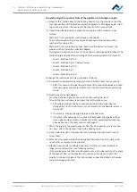
b) You may use the normal view/telephoto toggling lever of the vision box. With
regard to this, please also read the Overview of the machine partschapter , No.
11.
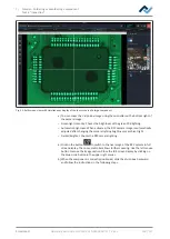
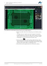
c) Activate the [Show red and green overlay] button to view the overlapping parts
of the green board image and of the red component image.
d) Use the four intensity and contrast controllers to optimise the image quality.
e) With the controller at the bottom on the right, you may adjust the vision box
zoom.
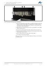
– First, correct the component rotation using the relevant rotary button. With re-
gard to this, please also read the Overview of the machine partschapter, No. 5.
– Then correct the display of the component size with the small arrow key and
with the [Component scaling] button. Arrow up/smaller = reduce red compon-
ent image. After making the correction, wait for the pipette motor to imple-
ment the change.
– Correct the PCB position with the two adjusting screws on the control panel.
The right screw changes the X direction, while the left adjusting screw changes
the Y direction. With regard to this, please also read the Overview of the ma-
chine partschapter, No. 2 and Nr. 8 on the control panel.
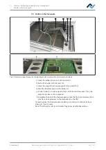
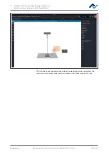
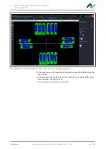
a) For instance, in case of large components, in order to enlarge the comparison
display of widely separated image areas click on the [Split optics] button. Now
click four times with the small blue rectangle on the four points that you wish
to enlarge.
Ersa GmbH
Operating instructions HR 550 XL EN 3BA00247-01 | Rev. 1
133 / 157

