4 | Transport, installation, storage, disposal
Screwing on a soldering nozzle and then removing the transport lock
4.10 Screwing on a soldering nozzle and then removing the transport lock
Before start-up, a soldering nozzle must be screwed to the pipette (heating head
underside). To do so, use one of the included soldering nozzles. Always select the
largest possible soldering nozzle for the component. Th soldering nozzle has been
fitted to the pipette. With regard to this, please read Chapter Overview of the ma-
chine parts.
After unpacking the Rework system, you will see that a transport lock is fitted un-
der the heating head. It supports the pipette retention mechanism to prevent any
damage from external forces. When attaching and removing soldering nozzles, the
transport lock must be applied to the pipette to compensate for the resulting strain
on the pipette retention mechanism. Otherwise material damage will occur! After
attaching or changing a soldering nozzle, unscrew the transport lock again.
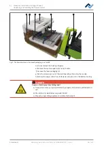
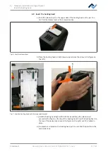
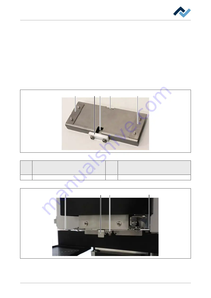
The transport lock consists of the following parts:
6
5
2
4
4
Fig. 8:
The transport lock in the removed state
2 Handle of the transport lock.
5 Plastic clamping piece, screwed twice. Not
needed for nozzle change. Only used to secure
the pipette when shipping the rework system
4 Two fixing strips, each screwed twice
6 Pipette recess
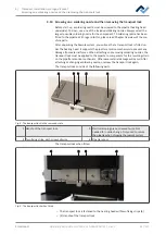
The transport lock when fitted:
3
2
4
4
Fig. 9:
The transport lock when fitted
– The transport lock is fastened to the heating head with two fixing strips (4)
– (2) Handle of the transport lock
Ersa GmbH
Operating instructions HR 550 XL EN 3BA00247-01 | Rev. 1
42 / 157


