Program Edit Mode
The Algorithm (ALG) Page
7-33
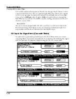
Each block of the algorithm represents a certain function in the signal path. In every non-
cascaded algorithm (see
Alt Input for Algorithms (Cascade Mode) on page 7-36
below), the
signal flows first through a one-stage DSP function that controls the pitch of the samples in
the keymap (this function is represented as a block labeled PITCH in the upper right-hand
corner of the display). In fact, the first DSP function in each algorithm always controls pitch,
even though it doesn’t apply in every instance and, as will be explained later in this section, it
is bypassed in cascaded algorithms. Similarly, the last DSP function always controls the final
amplitude of the signal (this function is represented as a block labeled AMP in the upper
right-hand corner of the display).
The number of function-parameters a DSP function can have depends on the relative size of
its function-block on the Algorithm page (four slots is the largest block size). For instance,
a function-block that is three slots long can have up to three function-parameters, whereas
a function-block that is two slots long can have up to two function-parameters. For each
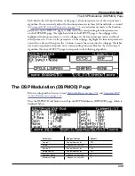
function-parameter, there’s a corresponding “subpage” on both the DSPCTL and DSPMOD
pages. On the DSPCTL subpages, there are fine adjust and hard-wired parameters with
which you can make fixed adjustments to the function-parameter. On the DSPMOD
subpages, there are programmable parameters that you can assign to any control source in
the Controller List to modulate the function-parameter. The various DSP parameter-types
are described in
Common DSP Control Parameters on page 7-33
. More information on the
The DSP Control (DSPCTL) Page on page 7-38
Modulation (DSPMOD) Page on page 7-39
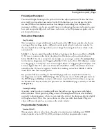
Highlighting any of the function-blocks on the ALG page and pressing the Edit button takes
you to the DSPCTL page.
Common DSP Control Parameters
The type of DSP function available for any function block depends on the algorithm. Some
of the specialized functions like the PANNER are always located just before the final AMP
function. Others, like the two-input functions, appear only in algorithms that are structured
for two-input functions.
You can change the nature of each layer of a program simply by assigning different DSP
functions to the layer’s algorithm. Your level of control goes much deeper than that, however.
Each DSP function has one or more parameters to which you can patch a variety of control
sources to modify the behavior of the DSP functions themselves.
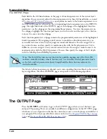
The parameters on the various control-input pages are very similar; in fact, there are six
parameters that appear on almost every page. Consequently we refer to them as the common
DSP control parameters. Although the parameters on the control-input pages differ slightly
from function to function, you can expect to see some or all of the common DSP control
parameters whenever you select the control-input page for any of the DSP functions.


