3-16
Disassembly/Assembly
Top Enclosure
Replacing the Front Panel Board
Note
: If you are replacing the Front Panel Board with another board, be sure to remove the four
screws that secure the LCD bezel to the board and install it on the new board.
1. Position the Front Panel Board onto the top enclosure, then raise the top enclosure up
slightly to verify that the spinknob and switch button caps are correctly positioned
through their openings in the top enclosure.
2. Place a PC board clamp in position. Align the center screw holes of the clamp with the
thread marks in the extrusion and install the two screws that secure the clamp. Repeat for
the other two clamps.
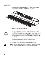
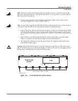
3. Install the screw that secures the front panel edge. See Figure 3-13.
4. If you removed the LCD Board, follow the procedure described on page 3-14 to replace it.
5. Connect the
fl
at ribbon cable from the Slider Board to J201.
6. If you have disconnected the cable from J202, reconnect it.
Warning
: If this cable has a small PC board, be very careful to plug the small PC board onto all
of the pins of J202. If it is offset by one pin either way, the Front Panel Board will be damaged!
7. Follow the procedure on page 3-10 to install the Connector Board.
8. Follow the procedure on page 3-8 to install the enclosure support wall.


